- 1. Administering and Maintaining the oVirt Environment
- 1.1. Global Configuration
- 1.2. Dashboard
- 1.3. Searches
- 1.3.1. Performing Searches in oVirt
- 1.3.2. Search Syntax and Examples
- 1.3.3. Search Auto-Completion
- 1.3.4. Search Result Type Options
- 1.3.5. Search Criteria
- 1.3.6. Search: Multiple Criteria and Wildcards
- 1.3.7. Search: Determining Search Order
- 1.3.8. Searching for Data Centers
- 1.3.9. Searching for Clusters
- 1.3.10. Searching for Hosts
- 1.3.11. Searching for Networks
- 1.3.12. Searching for Storage
- 1.3.13. Searching for Disks
- 1.3.14. Searching for Volumes
- 1.3.15. Searching for Virtual Machines
- 1.3.16. Searching for Pools
- 1.3.17. Searching for Templates
- 1.3.18. Searching for Users
- 1.3.19. Searching for Events
- 1.4. Bookmarks
- 1.5. Tags
- 2. Administering the Resources
- 2.1. Quality of Service
- 2.2. Data Centers
- 2.3. Clusters
- 2.4. Logical Networks
- 2.5. Hosts
- 2.6. Storage
- 2.6.1. About oVirt storage
- 2.6.2. Understanding Storage Domains
- 2.6.3. Preparing and Adding NFS Storage
- 2.6.4. Preparing and adding local storage
- 2.6.5. Preparing and Adding POSIX-compliant File System Storage
- 2.6.6. Preparing and Adding Block Storage
- 2.6.7. Preparing and Adding Gluster Storage
- 2.6.8. Importing Existing Storage Domains
- 2.6.9. Storage Tasks
- 2.7. Pools
- 2.8. Virtual Disks
- 2.9. External Providers
- 3. Administering the Environment
- 3.1. Administering the Self-Hosted Engine
- 3.1.1. Maintaining the Self-hosted engine
- 3.1.2. Administering the Engine Virtual Machine
- 3.1.3. Configuring Memory Slots Reserved for the Self-Hosted Engine on Additional Hosts
- 3.1.4. Adding Self-Hosted Engine Nodes to the oVirt Engine
- 3.1.5. Reinstalling an Existing Host as a Self-Hosted Engine Node
- 3.1.6. Booting the Engine Virtual Machine in Rescue Mode
- 3.1.7. Removing a Host from a Self-Hosted Engine Environment
- 3.1.8. Updating a Self-Hosted Engine
- 3.1.9. Changing the FQDN of the Engine in a Self-Hosted Engine
- 3.2. Backups and Migration
- 3.2.1. Backing Up and Restoring the oVirt Engine
- 3.2.2. Migrating the Data Warehouse to a Separate Machine
- 3.2.3. Backing Up and Restoring Virtual Machines Using a Backup Storage Domain
- 3.2.4. Backing Up and Restoring Virtual Machines Using the Backup and Restore API
- 3.2.5. Backing Up and Restoring Virtual Machines Using the Incremental Backup and Restore API
- 3.3. Setting up errata viewing with Red Hat Satellite
- 3.4. Renewing certificates before they expire
- 3.5. Automating Configuration Tasks using Ansible
- 3.6. Users and Roles
- 3.6.1. Introduction to Users
- 3.6.2. Introduction to Directory Servers
- 3.6.3. Configuring an External LDAP Provider
- 3.6.4. Configuring LDAP and Kerberos for Single Sign-on
- 3.6.5. Installing and Configuring Red Hat Single Sign-On
- 3.6.6. User Authorization
- 3.6.7. Administering User Tasks From the Administration Portal
- 3.6.8. Administering User Tasks From the Command Line
- 3.6.9. Configuring Additional Local Domains
- 3.7. Quotas and Service Level Agreement Policy
- 3.7.1. Introduction to Quota
- 3.7.2. Shared Quota and Individually Defined Quota
- 3.7.3. Quota Accounting
- 3.7.4. Enabling and Changing a Quota Mode in a Data Center
- 3.7.5. Creating a New Quota Policy
- 3.7.6. Explanation of Quota Threshold Settings
- 3.7.7. Assigning a Quota to an Object
- 3.7.8. Using Quota to Limit Resources by User
- 3.7.9. Editing Quotas
- 3.7.10. Removing Quotas
- 3.7.11. Service Level Agreement Policy Enforcement
- 3.8. Event Notifications
- 3.9. Utilities
- 3.1. Administering the Self-Hosted Engine
- 4. Gathering Information About the Environment
- 4.1. Monitoring and observability
- 4.2. Log Files
- 4.2.1. Engine Installation Log Files
- 4.2.2. oVirt Engine Log Files
- 4.2.3. SPICE Log Files
- 4.2.4. Host Log Files
- 4.2.5. Setting debug-level logging for oVirt services
- 4.2.6. Main configuration files for oVirt services
- 4.2.7. Setting Up a Host Logging Server
- 4.2.8. Enabling SyslogHandler to pass oVirt Engine logs to a remote syslog server
- Appendix A: VDSM Service and Hooks
- Installing a VDSM hook
- Supported VDSM Events
- The VDSM Hook Environment
- The VDSM Hook Domain XML Object
- Defining Custom Properties
- Setting Virtual Machine Custom Properties
- Evaluating Virtual Machine Custom Properties in a VDSM Hook
- Using the VDSM Hooking Module
- VDSM Hook Execution
- VDSM Hook Return Codes
- VDSM Hook Examples
- Appendix B: Custom Network Properties
- Appendix C: oVirt User Interface Plugins
- Appendix D: Enabling FIPS in oVirt
- Appendix E: oVirt and encrypted communication
- Appendix F: Proxies
- Appendix G: Branding
- Appendix H: System Accounts
- Appendix I: Legal notice
Administration Guide
1. Administering and Maintaining the oVirt Environment
The oVirt environment requires an administrator to keep it running. As an administrator, your tasks include:
-
Managing physical and virtual resources such as hosts and virtual machines. This includes upgrading and adding hosts, importing domains, converting virtual machines created on foreign hypervisors, and managing virtual machine pools.
-
Monitoring the overall system resources for potential problems such as extreme load on one of the hosts, insufficient memory or disk space, and taking any necessary actions (such as migrating virtual machines to other hosts to lessen the load or freeing resources by shutting down machines).
-
Responding to the new requirements of virtual machines (for example, upgrading the operating system or allocating more memory).
-
Managing customized object properties using tags.
-
Managing searches saved as public bookmarks.
-
Managing user setup and setting permission levels.
-
Troubleshooting for specific users or virtual machines for overall system functionality.
-
Generating general and specific reports.
1.1. Global Configuration
Accessed by clicking , the Configure window allows you to configure a number of global resources for your oVirt environment, such as users, roles, system permissions, scheduling policies, instance types, and MAC address pools. This window allows you to customize the way in which users interact with resources in the environment, and provides a central location for configuring options that can be applied to multiple clusters.
1.1.1. Roles
Roles are predefined sets of privileges that can be configured from oVirt Engine. Roles provide access and management permissions to different levels of resources in the data center, and to specific physical and virtual resources.
With multilevel administration, any permissions which apply to a container object also apply to all individual objects within that container. For example, when a host administrator role is assigned to a user on a specific host, the user gains permissions to perform any of the available host operations, but only on the assigned host. However, if the host administrator role is assigned to a user on a data center, the user gains permissions to perform host operations on all hosts within the cluster of the data center.
Creating a New Role
If the role you require is not on oVirt’s default list of roles, you can create a new role and customize it to suit your purposes.
-
Click . This opens the Configure window. The Roles tab is selected by default, showing a list of default User and Administrator roles, and any custom roles.
-
Click New.
-
Enter the Name and Description of the new role.
-
Select either Admin or User as the Account Type.
-
Use the Expand All or Collapse All buttons to view more or fewer of the permissions for the listed objects in the Check Boxes to Allow Action list. You can also expand or collapse the options for each object.
-
For each of the objects, select or clear the actions you want to permit or deny for the role you are setting up.
-
Click OK to apply the changes. The new role displays on the list of roles.
Editing or Copying a Role
You can change the settings for roles you have created, but you cannot change default roles. To change default roles, clone and modify them to suit your requirements.
-
Click . This opens the Configure window, which shows a list of default User and Administrator roles, as well as any custom roles.
-
Select the role you wish to change.
-
Click Edit or Copy. This opens the Edit Role or Copy Role window.
-
If necessary, edit the Name and Description of the role.
-
Use the Expand All or Collapse All buttons to view more or fewer of the permissions for the listed objects. You can also expand or collapse the options for each object.
-
For each of the objects, select or clear the actions you wish to permit or deny for the role you are editing.
-
Click OK to apply the changes you have made.
User Role and Authorization Examples
The following examples illustrate how to apply authorization controls for various scenarios, using the different features of the authorization system described in this chapter.
Sarah is the system administrator for the accounts department of a company. All the virtual resources for her department are organized under a oVirt cluster called Accounts. She is assigned the ClusterAdmin role on the accounts cluster. This enables her to manage all virtual machines in the cluster, since the virtual machines are child objects of the cluster. Managing the virtual machines includes editing, adding, or removing virtual resources such as disks, and taking snapshots. It does not allow her to manage any resources outside this cluster. Because ClusterAdmin is an administrator role, it allows her to use the Administration Portal or the VM Portal to manage these resources.
John is a software developer in the accounts department. He uses virtual machines to build and test his software. Sarah has created a virtual desktop called johndesktop for him. John is assigned the UserVmManager role on the johndesktop virtual machine. This allows him to access this single virtual machine using the VM Portal. Because he has UserVmManager permissions, he can modify the virtual machine. Because UserVmManager is a user role, it does not allow him to use the Administration Portal.
Penelope is an office manager. In addition to her own responsibilities, she occasionally helps the HR manager with recruitment tasks, such as scheduling interviews and following up on reference checks. As per corporate policy, Penelope needs to use a particular application for recruitment tasks.
While Penelope has her own machine for office management tasks, she wants to create a separate virtual machine to run the recruitment application. She is assigned PowerUserRole permissions for the data center in which her new virtual machine will reside. This is because to create a new virtual machine, she needs to make changes to several components within the data center, including creating the virtual disk in the storage domain.
Note that this is not the same as assigning DataCenterAdmin privileges to Penelope. As a PowerUser for a data center, Penelope can log in to the VM Portal and perform virtual machine-specific actions on virtual machines within the data center. She cannot perform data center-level operations such as attaching hosts or storage to a data center.
Chris works as the network administrator in the IT department. Her day-to-day responsibilities include creating, manipulating, and removing networks in the department’s oVirt environment. For her role, she requires administrative privileges on the resources and on the networks of each resource. For example, if Chris has NetworkAdmin privileges on the IT department’s data center, she can add and remove networks in the data center, and attach and detach networks for all virtual machines belonging to the data center.
Rachel works in the IT department, and is responsible for managing user accounts in oVirt. She needs permission to add user accounts and assign them the appropriate roles and permissions. She does not use any virtual machines herself, and should not have access to administration of hosts, virtual machines, clusters or data centers. There is no built-in role which provides her with this specific set of permissions. A custom role must be created to define the set of permissions appropriate to Rachel’s position.
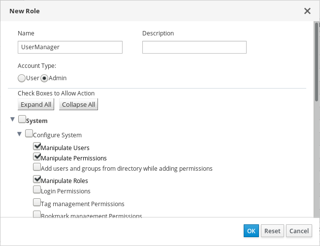
The UserManager custom role shown above allows manipulation of users, permissions and roles. These actions are organized under System - the top level object of the hierarchy shown in Object Hierarchy. This means they apply to all other objects in the system. The role is set to have an Account Type of Admin. This means that when she is assigned this role, Rachel can use both the Administration Portal and the VM Portal.
1.1.2. System Permissions
Permissions enable users to perform actions on objects, where objects are either individual objects or container objects. Any permissions that apply to a container object also apply to all members of that container.

User Properties
Roles and permissions are the properties of the user. Roles are predefined sets of privileges that permit access to different levels of physical and virtual resources. Multilevel administration provides a finely grained hierarchy of permissions. For example, a data center administrator has permissions to manage all objects in the data center, while a host administrator has system administrator permissions to a single physical host. A user can have permissions to use a single virtual machine but not make any changes to the virtual machine configurations, while another user can be assigned system permissions to a virtual machine.
User and Administrator Roles
oVirt provides a range of pre-configured roles, from an administrator with system-wide permissions to an end user with access to a single virtual machine. While you cannot change or remove the default roles, you can clone and customize them, or create new roles according to your requirements. There are two types of roles:
-
Administrator Role: Allows access to the Administration Portal for managing physical and virtual resources. An administrator role confers permissions for actions to be performed in the VM Portal; however, it has no bearing on what a user can see in the VM Portal.
-
User Role: Allows access to the VM Portal for managing and accessing virtual machines and templates. A user role determines what a user can see in the VM Portal. Permissions granted to a user with an administrator role are reflected in the actions available to that user in the VM Portal.
User Roles Explained
The table below describes basic user roles which confer permissions to access and configure virtual machines in the VM Portal.
| Role | Privileges | Notes |
|---|---|---|
UserRole |
Can access and use virtual machines and pools. |
Can log in to the VM Portal, use assigned virtual machines and pools, view virtual machine state and details. |
PowerUserRole |
Can create and manage virtual machines and templates. |
Apply this role to a user for the whole environment with the Configure window, or for specific data centers or clusters. For example, if a PowerUserRole is applied on a data center level, the PowerUser can create virtual machines and templates in the data center. |
UserVmManager |
System administrator of a virtual machine. |
Can manage virtual machines and create and use snapshots. A user who creates a virtual machine in the VM Portal is automatically assigned the UserVmManager role on the machine. |
The table below describes advanced user roles which allow you to do more fine tuning of permissions for resources in the VM Portal.
| Role | Privileges | Notes |
|---|---|---|
UserTemplateBasedVm |
Limited privileges to only use Templates. |
Can use templates to create virtual machines. |
DiskOperator |
Virtual disk user. |
Can use, view and edit virtual disks. Inherits permissions to use the virtual machine to which the virtual disk is attached. |
VmCreator |
Can create virtual machines in the VM Portal. |
This role is not applied to a specific virtual machine; apply this role to a user for the whole environment with the Configure window. Alternatively apply this role for specific data centers or clusters. When applying this role to a cluster, you must also apply the DiskCreator role on an entire data center, or on specific storage domains. |
TemplateCreator |
Can create, edit, manage and remove virtual machine templates within assigned resources. |
This role is not applied to a specific template; apply this role to a user for the whole environment with the Configure window. Alternatively apply this role for specific data centers, clusters, or storage domains. |
DiskCreator |
Can create, edit, manage and remove virtual disks within assigned clusters or data centers. |
This role is not applied to a specific virtual disk; apply this role to a user for the whole environment with the Configure window. Alternatively apply this role for specific data centers or storage domains. |
TemplateOwner |
Can edit and delete the template, assign and manage user permissions for the template. |
This role is automatically assigned to the user who creates a template. Other users who do not have TemplateOwner permissions on a template cannot view or use the template. |
VnicProfileUser |
Logical network and network interface user for virtual machine and template. |
Can attach or detach network interfaces from specific logical networks. |
Administrator Roles Explained
The table below describes basic administrator roles which confer permissions to access and configure resources in the Administration Portal.
| Role | Privileges | Notes |
|---|---|---|
SuperUser |
System Administrator of the oVirt environment. |
Has full permissions across all objects and levels, can manage all objects across all data centers. |
ClusterAdmin |
Cluster Administrator. |
Possesses administrative permissions for all objects underneath a specific cluster. |
DataCenterAdmin |
Data Center Administrator. |
Possesses administrative permissions for all objects underneath a specific data center except for storage. |
|
Do not use the administrative user for the directory server as the oVirt administrative user. Create a user in the directory server specifically for use as the oVirt administrative user. |
The table below describes advanced administrator roles which allow you to do more fine tuning of permissions for resources in the Administration Portal.
| Role | Privileges | Notes |
|---|---|---|
TemplateAdmin |
Administrator of a virtual machine template. |
Can create, delete, and configure the storage domains and network details of templates, and move templates between domains. |
StorageAdmin |
Storage Administrator. |
Can create, delete, configure, and manage an assigned storage domain. |
HostAdmin |
Host Administrator. |
Can attach, remove, configure, and manage a specific host. |
NetworkAdmin |
Network Administrator. |
Can configure and manage the network of a particular data center or cluster. A network administrator of a data center or cluster inherits network permissions for virtual pools within the cluster. |
VmPoolAdmin |
System Administrator of a virtual pool. |
Can create, delete, and configure a virtual pool; assign and remove virtual pool users; and perform basic operations on a virtual machine in the pool. |
GlusterAdmin |
Gluster Storage Administrator. |
Can create, delete, configure, and manage Gluster storage volumes. |
VmImporterExporter |
Import and export Administrator of a virtual machine. |
Can import and export virtual machines. Able to view all virtual machines and templates exported by other users. |
Assigning an Administrator or User Role to a Resource
Assign administrator or user roles to resources to allow users to access or manage that resource.
-
Find and click the resource’s name. This opens the details view.
-
Click the Permissions tab to list the assigned users, each user’s role, and the inherited permissions for the selected resource.
-
Click Add.
-
Enter the name or user name of an existing user into the Search text box and click Go. Select a user from the resulting list of possible matches.
-
Select a role from the Role to Assign drop-down list.
-
Click OK.
The user now has the inherited permissions of that role enabled for that resource.
|
Avoid assigning global permissions to regular users on resources such as clusters because permissions are automatically inherited by resources that are lower in a system’s hierarchy. Set Assigning global permissions can cause two problems due to the inheritance of permissions:
Therefore, it is strongly recommended to set |
Removing an Administrator or User Role from a Resource
Remove an administrator or user role from a resource; the user loses the inherited permissions associated with the role for that resource.
-
Find and click the resource’s name. This opens the details view.
-
Click the Permissions tab to list the assigned users, the user’s role, and the inherited permissions for the selected resource.
-
Select the user to remove from the resource.
-
Click Remove.
-
Click OK.
Managing System Permissions for a Data Center
As the SuperUser, the system administrator manages all aspects of the Administration Portal. More specific administrative roles can be assigned to other users. These restricted administrator roles are useful for granting a user administrative privileges that limit them to a specific resource. For example, a DataCenterAdmin role has administrator privileges only for the assigned data center with the exception of the storage for that data center, and a ClusterAdmin has administrator privileges only for the assigned cluster.
A data center administrator is a system administration role for a specific data center only. This is useful in virtualization environments with multiple data centers where each data center requires an administrator. The DataCenterAdmin role is a hierarchical model; a user assigned the data center administrator role for a data center can manage all objects in the data center with the exception of storage for that data center. Use the Configure button in the header bar to assign a data center administrator for all data centers in the environment.
The data center administrator role permits the following actions:
-
Create and remove clusters associated with the data center.
-
Add and remove hosts, virtual machines, and pools associated with the data center.
-
Edit user permissions for virtual machines associated with the data center.
|
You can only assign roles and permissions to existing users. |
You can change the system administrator of a data center by removing the existing system administrator and adding the new system administrator.
Data Center Administrator Roles Explained
Data Center Permission Roles
The table below describes the administrator roles and privileges applicable to data center administration.
| Role | Privileges | Notes |
|---|---|---|
DataCenterAdmin |
Data Center Administrator |
Can use, create, delete, manage all physical and virtual resources within a specific data center except for storage, including clusters, hosts, templates and virtual machines. |
NetworkAdmin |
Network Administrator |
Can configure and manage the network of a particular data center. A network administrator of a data center inherits network permissions for virtual machines within the data center as well. |
Managing System Permissions for a Cluster
As the SuperUser, the system administrator manages all aspects of the Administration Portal. More specific administrative roles can be assigned to other users. These restricted administrator roles are useful for granting a user administrative privileges that limit them to a specific resource. For example, a DataCenterAdmin role has administrator privileges only for the assigned data center with the exception of the storage for that data center, and a ClusterAdmin has administrator privileges only for the assigned cluster.
A cluster administrator is a system administration role for a specific cluster only. This is useful in data centers with multiple clusters, where each cluster requires a system administrator. The ClusterAdmin role is a hierarchical model: a user assigned the cluster administrator role for a cluster can manage all objects in the cluster. Use the Configure button in the header bar to assign a cluster administrator for all clusters in the environment.
The cluster administrator role permits the following actions:
-
Create and remove associated clusters.
-
Add and remove hosts, virtual machines, and pools associated with the cluster.
-
Edit user permissions for virtual machines associated with the cluster.
|
You can only assign roles and permissions to existing users. |
You can also change the system administrator of a cluster by removing the existing system administrator and adding the new system administrator.
Cluster Administrator Roles Explained
Cluster Permission Roles
The table below describes the administrator roles and privileges applicable to cluster administration.
| Role | Privileges | Notes |
|---|---|---|
ClusterAdmin |
Cluster Administrator |
Can use, create, delete, manage all physical and virtual resources in a specific cluster, including hosts, templates and virtual machines. Can configure network properties within the cluster such as designating display networks, or marking a network as required or non-required. However, a ClusterAdmin does not have permissions to attach or detach networks from a cluster, to do so NetworkAdmin permissions are required. |
NetworkAdmin |
Network Administrator |
Can configure and manage the network of a particular cluster. A network administrator of a cluster inherits network permissions for virtual machines within the cluster as well. |
Managing System Permissions for a Network
As the SuperUser, the system administrator manages all aspects of the Administration Portal. More specific administrative roles can be assigned to other users. These restricted administrator roles are useful for granting a user administrative privileges that limit them to a specific resource. For example, a DataCenterAdmin role has administrator privileges only for the assigned data center with the exception of the storage for that data center, and a ClusterAdmin has administrator privileges only for the assigned cluster.
A network administrator is a system administration role that can be applied for a specific network, or for all networks on a data center, cluster, host, virtual machine, or template. A network user can perform limited administration roles, such as viewing and attaching networks on a specific virtual machine or template. You can use the Configure button in the header bar to assign a network administrator for all networks in the environment.
The network administrator role permits the following actions:
-
Create, edit and remove networks.
-
Edit the configuration of the network, including configuring port mirroring.
-
Attach and detach networks from resources including clusters and virtual machines.
The user who creates a network is automatically assigned NetworkAdmin permissions on the created network. You can also change the administrator of a network by removing the existing administrator and adding the new administrator.
Network Administrator and User Roles Explained
Network Permission Roles
The table below describes the administrator and user roles and privileges applicable to network administration.
| Role | Privileges | Notes |
|---|---|---|
NetworkAdmin |
Network Administrator for data center, cluster, host, virtual machine, or template. The user who creates a network is automatically assigned NetworkAdmin permissions on the created network. |
Can configure and manage the network of a particular data center, cluster, host, virtual machine, or template. A network administrator of a data center or cluster inherits network permissions for virtual pools within the cluster. To configure port mirroring on a virtual machine network, apply the NetworkAdmin role on the network and the UserVmManager role on the virtual machine. |
VnicProfileUser |
Logical network and network interface user for virtual machine and template. |
Can attach or detach network interfaces from specific logical networks. |
Managing System Permissions for a Host
As the SuperUser, the system administrator manages all aspects of the Administration Portal. More specific administrative roles can be assigned to other users. These restricted administrator roles are useful for granting a user administrative privileges that limit them to a specific resource. For example, a DataCenterAdmin role has administrator privileges only for the assigned data center with the exception of the storage for that data center, and a ClusterAdmin has administrator privileges only for the assigned cluster.
A host administrator is a system administration role for a specific host only. This is useful in clusters with multiple hosts, where each host requires a system administrator. You can use the Configure button in the header bar to assign a host administrator for all hosts in the environment.
The host administrator role permits the following actions:
-
Edit the configuration of the host.
-
Set up the logical networks.
-
Remove the host.
You can also change the system administrator of a host by removing the existing system administrator and adding the new system administrator.
Host Administrator Roles Explained
Host Permission Roles
The table below describes the administrator roles and privileges applicable to host administration.
| Role | Privileges | Notes |
|---|---|---|
HostAdmin |
Host Administrator |
Can configure, manage, and remove a specific host. Can also perform network-related operations on a specific host. |
Managing System Permissions for a Storage Domain
As the SuperUser, the system administrator manages all aspects of the Administration Portal. More specific administrative roles can be assigned to other users. These restricted administrator roles are useful for granting a user administrative privileges that limit them to a specific resource. For example, a DataCenterAdmin role has administrator privileges only for the assigned data center with the exception of the storage for that data center, and a ClusterAdmin has administrator privileges only for the assigned cluster.
A storage administrator is a system administration role for a specific storage domain only. This is useful in data centers with multiple storage domains, where each storage domain requires a system administrator. Use the Configure button in the header bar to assign a storage administrator for all storage domains in the environment.
The storage domain administrator role permits the following actions:
-
Edit the configuration of the storage domain.
-
Move the storage domain into maintenance mode.
-
Remove the storage domain.
|
You can only assign roles and permissions to existing users. |
You can also change the system administrator of a storage domain by removing the existing system administrator and adding the new system administrator.
Storage Administrator Roles Explained
Storage Domain Permission Roles
The table below describes the administrator roles and privileges applicable to storage domain administration.
| Role | Privileges | Notes |
|---|---|---|
StorageAdmin |
Storage Administrator |
Can create, delete, configure and manage a specific storage domain. |
GlusterAdmin |
Gluster Storage Administrator |
Can create, delete, configure and manage Gluster storage volumes. |
Managing System Permissions for a Virtual Machine Pool
As the SuperUser, the system administrator manages all aspects of the Administration Portal. More specific administrative roles can be assigned to other users. These restricted administrator roles are useful for granting a user administrative privileges that limit them to a specific resource. For example, a DataCenterAdmin role has administrator privileges only for the assigned data center with the exception of the storage for that data center, and a ClusterAdmin has administrator privileges only for the assigned cluster.
A virtual machine pool administrator is a system administration role for virtual machine pools in a data center. This role can be applied to specific virtual machine pools, to a data center, or to the whole virtualized environment; this is useful to allow different users to manage certain virtual machine pool resources.
The virtual machine pool administrator role permits the following actions:
-
Create, edit, and remove pools.
-
Add and detach virtual machines from the pool.
|
You can only assign roles and permissions to existing users. |
Virtual Machine Pool Administrator Roles Explained
Pool Permission Roles
The table below describes the administrator roles and privileges applicable to pool administration.
| Role | Privileges | Notes |
|---|---|---|
VmPoolAdmin |
System Administrator role of a virtual pool. |
Can create, delete, and configure a virtual pool, assign and remove virtual pool users, and perform basic operations on a virtual machine. |
ClusterAdmin |
Cluster Administrator |
Can use, create, delete, manage all virtual machine pools in a specific cluster. |
Managing System Permissions for a Virtual Disk
As the SuperUser, the system administrator manages all aspects of the Administration Portal. More specific administrative roles can be assigned to other users. These restricted administrator roles are useful for granting a user administrative privileges that limit them to a specific resource. For example, a DataCenterAdmin role has administrator privileges only for the assigned data center with the exception of the storage for that data center, and a ClusterAdmin has administrator privileges only for the assigned cluster.
oVirt Engine provides two default virtual disk user roles, but no default virtual disk administrator roles. One of these user roles, the DiskCreator role, enables the administration of virtual disks from the VM Portal. This role can be applied to specific virtual machines, to a data center, to a specific storage domain, or to the whole virtualized environment; this is useful to allow different users to manage different virtual resources.
The virtual disk creator role permits the following actions:
-
Create, edit, and remove virtual disks associated with a virtual machine or other resources.
-
Edit user permissions for virtual disks.
|
You can only assign roles and permissions to existing users. |
Virtual Disk User Roles Explained
Virtual Disk User Permission Roles
The table below describes the user roles and privileges applicable to using and administrating virtual disks in the VM Portal.
| Role | Privileges | Notes |
|---|---|---|
DiskOperator |
Virtual disk user. |
Can use, view and edit virtual disks. Inherits permissions to use the virtual machine to which the virtual disk is attached. |
DiskCreator |
Can create, edit, manage and remove virtual disks within assigned clusters or data centers. |
This role is not applied to a specific virtual disk; apply this role to a user for the whole environment with the Configure window. Alternatively apply this role for specific data centers, clusters, or storage domains. |
Setting a Legacy SPICE Cipher
SPICE consoles use FIPS-compliant encryption by default, with a cipher string. The default SPICE cipher string is:
kECDHE+FIPS:kDHE+FIPS:kRSA+FIPS:!eNULL:!aNULL
This string is generally sufficient. However, if you have a virtual machine with an older operating system or SPICE client, where either one or the other does not support FIPS-compliant encryption, you must use a weaker cipher string. Otherwise, a connection security error may occur if you install a new cluster or a new host in an existing cluster and try to connect to that virtual machine.
You can change the cipher string by using an Ansible playbook.
Changing the cipher string
-
On the Engine machine, create a file in the directory
/usr/share/ovirt-engine/playbooks. For example:# vim /usr/share/ovirt-engine/playbooks/change-spice-cipher.yml -
Enter the following in the file and save it:
name: oVirt - setup weaker SPICE encryption for old clients hosts: hostname vars: host_deploy_spice_cipher_string: 'DEFAULT:-RC4:-3DES:-DES' roles: - ovirt-host-deploy-spice-encryption -
Run the file you just created:
# ansible-playbook -l hostname /usr/share/ovirt-engine/playbooks/change-spice-cipher.yml
Alternatively, you can reconfigure the host with the Ansible playbook ovirt-host-deploy using the --extra-vars option with the variable host_deploy_spice_cipher_string:
# ansible-playbook -l hostname \
  --extra-vars host_deploy_spice_cipher_string=”DEFAULT:-RC4:-3DES:-DES” \
  /usr/share/ovirt-engine/playbooks/ovirt-host-deploy.yml
1.1.3. Scheduling Policies
A scheduling policy is a set of rules that defines the logic by which virtual machines are distributed amongst hosts in the cluster that scheduling policy is applied to. Scheduling policies determine this logic via a combination of filters, weightings, and a load balancing policy. The filter modules apply hard enforcement and filter out hosts that do not meet the conditions specified by that filter. The weights modules apply soft enforcement, and are used to control the relative priority of factors considered when determining the hosts in a cluster on which a virtual machine can run.
The oVirt Engine provides five default scheduling policies: Evenly_Distributed, Cluster_Maintenance, None, Power_Saving, and VM_Evenly_Distributed. You can also define new scheduling policies that provide fine-grained control over the distribution of virtual machines. Regardless of the scheduling policy, a virtual machine will not start on a host with an overloaded CPU. By default, a host’s CPU is considered overloaded if it has a load of more than 80% for 2 minutes, but these values can be changed using scheduling policies. See Scheduling Policies in the Administration Guide for more information about the properties of each scheduling policy.
The Evenly_Distributed scheduling policy distributes the memory and CPU processing load evenly across all hosts in the cluster. Additional virtual machines attached to a host will not start if that host has reached the defined CpuOverCommitDurationMinutes, HighUtilization, VCpuToPhysicalCpuRatio, or MaxFreeMemoryForOverUtilized.
The VM_Evenly_Distributed scheduling policy distributes virtual machines evenly between hosts based on a count of the virtual machines. The cluster is considered unbalanced if any host is running more virtual machines than the HighVmCount and there is at least one host with a virtual machine count that falls outside of the MigrationThreshold.
The Power_Saving scheduling policy distributes the memory and CPU processing load across a subset of available hosts to reduce power consumption on underutilized hosts. Hosts with a CPU load below the low utilization value for longer than the defined time interval will migrate all virtual machines to other hosts so that it can be powered down. Additional virtual machines attached to a host will not start if that host has reached the defined high utilization value.
Set the None policy to have no load or power sharing between hosts for running virtual machines. This is the default mode. When a virtual machine is started, the memory and CPU processing load is spread evenly across all hosts in the cluster. Additional virtual machines attached to a host will not start if that host has reached the defined CpuOverCommitDurationMinutes, HighUtilization, or MaxFreeMemoryForOverUtilized.
The Cluster_Maintenance scheduling policy limits activity in a cluster during maintenance tasks. When the Cluster_Maintenance policy is set, no new virtual machines may be started, except highly available virtual machines. If host failure occurs, highly available virtual machines will restart properly and any virtual machine can migrate.
Creating a Scheduling Policy
You can create new scheduling policies to control the logic by which virtual machines are distributed amongst a given cluster in your oVirt environment.
-
Click .
-
Click the Scheduling Policies tab.
-
Click New.
-
Enter a Name and Description for the scheduling policy.
-
Configure filter modules:
-
In the Filter Modules section, drag and drop the preferred filter modules to apply to the scheduling policy from the Disabled Filters section into the Enabled Filters section.
-
Specific filter modules can also be set as the First, to be given highest priority, or Last, to be given lowest priority, for basic optimization. To set the priority, right-click any filter module, hover the cursor over Position and select First or Last.
-
-
Configure weight modules:
-
In the Weights Modules section, drag and drop the preferred weights modules to apply to the scheduling policy from the Disabled Weights section into the Enabled Weights & Factors section.
-
Use the + and - buttons to the left of the enabled weight modules to increase or decrease the weight of those modules.
-
-
Specify a load balancing policy:
-
From the drop-down menu in the Load Balancer section, select the load balancing policy to apply to the scheduling policy.
-
From the drop-down menu in the Properties section, select a load balancing property to apply to the scheduling policy and use the text field to the right of that property to specify a value.
-
Use the + and - buttons to add or remove additional properties.
-
-
Click OK.
Explanation of Settings in the New Scheduling Policy and Edit Scheduling Policy Window
The following details the different options available in the New Scheduling Policy and Edit Scheduling Policy windows.
Name: The name of the scheduling policy. This is the name used to refer to the scheduling policy in the oVirt Engine.
Description: A description of the scheduling policy. This field is recommended but not mandatory.
Filter Modules: A set of filters for controlling the hosts on which a virtual machine in a cluster can run. Enabling a filter will filter out hosts that do not meet the conditions specified by that filter, as outlined below:
| Filter Modules marked with represent units that are mandatory since 4.4.0. From that version onward these are always enabled and will not be displayed in the UI. |
| Filter Name | Description |
|---|---|
|
Virtual machines being started on the host that are not configured for high availability filter out the host |
|
Hosts which do not satisfy the CPU pinning definition. |
|
Prevents migration to the same host. |
|
Hosts with CPU usage that is above the defined HighUtilization threshold for the interval defined by the CpuOverCommitDurationMinutes. |
|
Hosts other than the host to which the virtual machine is pinned. |
|
Hosts that do not meet the CPU topology of the virtual machine. |
|
Hosts that do not meet the affinity rules defined for the virtual machine. |
|
Hosts that do not have NUMA nodes that can accommodate the virtual machine vNUMA nodes in terms of resources. |
|
Hosts that are running an earlier version of the operating system than the host that the virtual machine currently runs on. |
|
Hosts that do not provide the required mediated device (mDev). |
|
Hosts that do not have sufficient memory to run the virtual machine. |
|
Hosts with fewer CPUs than the number assigned to the virtual machine. |
|
Reserves space for the Engine virtual machine on a specified number of self-hosted engine nodes. |
|
Hosts that are not swapping within the threshold. |
|
Hosts that do not support virtual machines configured with storage leases. |
|
Group of hosts that do not meet the conditions specified for a virtual machine that is a member of an affinity group. For example, that virtual machines in an affinity group must run on one of the hosts in a group or on a separate host that is excluded from the group. |
|
Hosts that do not support host devices required by the virtual machine. |
|
Forces the Engine virtual machine in a self-hosted engine environment to run only on hosts with a positive high availability score. |
|
Hosts which do not have proper emulated machine support. |
|
Hosts that do not meet the required number of Huge Pages needed for the virtual machine’s memory. |
|
Hosts that do not have virtual machines with the same TSC frequency as the host currently running the virtual machine. |
|
Hosts on which networks required by the network interface controller of a virtual machine are not installed, or on which the cluster’s display network is not installed. |
|
Hosts that do not have the correct cluster compatibility version support. |
|
Runs VMs only on hosts with a hooks required by VM’s configuration |
Weight Modules: A set of weightings for controlling the relative priority of factors considered when determining the hosts in a cluster on which a virtual machine can run.
| Weight Name | Description |
|---|---|
|
Weights hosts in accordance with the affinity groups defined for virtual machines. This weight module determines how likely virtual machines in an affinity group are to run on the same host or on separate hosts in accordance with the parameters of that affinity group. |
|
Weight hosts in accordance with their operating system version. The weight penalizes hosts with earlier operating systems more than hosts with the same operating system as the host that the virtual machine is currently running on. This ensures that priority is always given to hosts with later operating systems. |
|
Weights hosts in accordance with their CPU usage, giving priority to hosts with lower CPU usage. |
|
Prefers hosts that have more or an equal number of sockets, cores and threads than the VM. |
|
Weights hosts in accordance with their high availability score. |
|
Weights hosts in accordance with their CPU usage, giving priority to hosts with higher CPU usage. |
|
Weights hosts in accordance to pinning compatibility. When a virtual machine has both vNUMA and pinning defined, this weight module gives preference to hosts whose CPU pinning does not clash with the vNUMA pinning. |
|
Weights hosts in accordance with the affinity groups defined for virtual machines. This weight module determines how likely virtual machines in an affinity group are to run on one of the hosts in a group or on a separate host that is excluded from the group. |
|
Weights hosts in accordance with the number of virtual machines running on those hosts. |
|
Weights hosts in accordance with their high availability score. |
|
Weights hosts in accordance with their memory usage, giving priority to hosts with higher available memory. |
|
Weights hosts in accordance to whether a virtual machine fits into a single NUMA node. When a virtual machine does not have vNUMA defined, this weight module gives preference to hosts that can fit the virtual machine into a single physical NUMA. |
|
Preferred hosts have priority during virtual machine setup. |
|
Weights hosts in accordance with their memory usage, giving priority to hosts with higher memory usage. |
Load Balancer: This drop-down menu allows you to select a load balancing module to apply. Load balancing modules determine the logic used to migrate virtual machines from hosts experiencing high usage to hosts experiencing lower usage.
Properties: This drop-down menu allows you to add or remove properties for load balancing modules, and is only available when you have selected a load balancing module for the scheduling policy. No properties are defined by default, and the properties that are available are specific to the load balancing module that is selected. Use the + and - buttons to add or remove additional properties to or from the load balancing module.
1.1.4. Instance Types
Instance types can be used to define the hardware configuration of a virtual machine. Selecting an instance type when creating or editing a virtual machine will automatically fill in the hardware configuration fields. This allows users to create multiple virtual machines with the same hardware configuration without having to manually fill in every field.
| Support for instance types is now deprecated, and will be removed in a future release. |
A set of predefined instance types are available by default, as outlined in the following table:
| Name | Memory | vCPUs |
|---|---|---|
Tiny |
512 MB |
1 |
Small |
2 GB |
1 |
Medium |
4 GB |
2 |
Large |
8 GB |
2 |
XLarge |
16 GB |
4 |
Administrators can also create, edit, and remove instance types from the Instance Types tab of the Configure window.
Fields in the New Virtual Machine and Edit Virtual Machine windows that are bound to an instance type have a chain link image next to them ( ). If the value of one of these fields is changed, the virtual machine will be detached from the instance type, changing to Custom, and the chain will appear broken (
 ). However, if the value is changed back, the chain will relink and the instance type will move back to the selected one.
Creating Instance Types
Administrators can create new instance types, which can then be selected by users when creating or editing virtual machines.
-
Click .
-
Click the Instance Types tab.
-
Click New.
-
Enter a Name and Description for the instance type.
-
Click Show Advanced Options and configure the instance type’s settings as required. The settings that appear in the New Instance Type window are identical to those in the New Virtual Machine window, but with the relevant fields only. See Explanation of Settings in the New Virtual Machine and Edit Virtual Machine Windows in the Virtual Machine Management Guide.
-
Click OK.
The new instance type will appear in the Instance Types tab in the Configure window, and can be selected from the Instance Type drop-down list when creating or editing a virtual machine.
Editing Instance Types
Administrators can edit existing instance types from the Configure window.
-
Click .
-
Click the Instance Types tab.
-
Select the instance type to be edited.
-
Click Edit.
-
Change the settings as required.
-
Click OK.
The configuration of the instance type is updated. When a new virtual machine based on this instance type is created, or when an existing virtual machine based on this instance type is updated, the new configuration is applied.
Existing virtual machines based on this instance type will display fields, marked with a chain icon, that will be updated. If the existing virtual machines were running when the instance type was changed, the orange Pending Changes icon will appear beside them and the fields with the chain icon will be updated at the next restart.
Removing Instance Types
-
Click .
-
Click the Instance Types tab.
-
Select the instance type to be removed.
-
Click Remove.
-
If any virtual machines are based on the instance type to be removed, a warning window listing the attached virtual machines will appear. To continue removing the instance type, select the Approve Operation check box. Otherwise click Cancel.
-
Click OK.
The instance type is removed from the Instance Types list and can no longer be used when creating a new virtual machine. Any virtual machines that were attached to the removed instance type will now be attached to Custom (no instance type).
1.1.5. MAC Address Pools
MAC address pools define the range(s) of MAC addresses allocated for each cluster. A MAC address pool is specified for each cluster. By using MAC address pools, oVirt can automatically generate and assign MAC addresses to new virtual network devices, which helps to prevent MAC address duplication. MAC address pools are more memory efficient when all MAC addresses related to a cluster are within the range for the assigned MAC address pool.
The same MAC address pool can be shared by multiple clusters, but each cluster has a single MAC address pool assigned. A default MAC address pool is created by oVirt and is used if another MAC address pool is not assigned. For more information about assigning MAC address pools to clusters see Creating a New Cluster.
|
If more than one oVirt cluster shares a network, do not rely solely on the default MAC address pool because the virtual machines of each cluster will try to use the same range of MAC addresses, leading to conflicts. To avoid MAC address conflicts, check the MAC address pool ranges to ensure that each cluster is assigned a unique MAC address range. |
The MAC address pool assigns the next available MAC address following the last address that was returned to the pool. If there are no further addresses left in the range, the search starts again from the beginning of the range. If there are multiple MAC address ranges with available MAC addresses defined in a single MAC address pool, the ranges take turns in serving incoming requests in the same way available MAC addresses are selected.
Creating MAC Address Pools
You can create new MAC address pools.
-
Click .
-
Click the MAC Address Pools tab.
-
Click Add.
-
Enter the Name and Description of the new MAC address pool.
-
Select the Allow Duplicates check box to allow a MAC address to be used multiple times in a pool. The MAC address pool will not automatically use a duplicate MAC address, but enabling the duplicates option means a user can manually use a duplicate MAC address.
If one MAC address pool has duplicates disabled, and another has duplicates enabled, each MAC address can be used once in the pool with duplicates disabled but can be used multiple times in the pool with duplicates enabled.
-
Enter the required MAC Address Ranges. To enter multiple ranges click the plus button next to the From and To fields.
-
Click OK.
Editing MAC Address Pools
You can edit MAC address pools to change the details, including the range of MAC addresses available in the pool and whether duplicates are allowed.
-
Click .
-
Click the MAC Address Pools tab.
-
Select the MAC address pool to be edited.
-
Click Edit.
-
Change the Name, Description, Allow Duplicates, and MAC Address Ranges fields as required.
When a MAC address range is updated, the MAC addresses of existing NICs are not reassigned. MAC addresses that were already assigned, but are outside of the new MAC address range, are added as user-specified MAC addresses and are still tracked by that MAC address pool.
-
Click OK.
Editing MAC Address Pool Permissions
After a MAC address pool has been created, you can edit its user permissions. The user permissions control which data centers can use the MAC address pool. See Roles for more information on adding new user permissions.
-
Click .
-
Click the MAC Address Pools tab.
-
Select the required MAC address pool.
-
Edit the user permissions for the MAC address pool:
-
To add user permissions to a MAC address pool:
-
Click Add in the user permissions pane at the bottom of the Configure window.
-
Search for and select the required users.
-
Select the required role from the Role to Assign drop-down list.
-
Click OK to add the user permissions.
-
-
To remove user permissions from a MAC address pool:
-
Select the user permission to be removed in the user permissions pane at the bottom of the Configure window.
-
Click Remove to remove the user permissions.
-
-
Removing MAC Address Pools
You can remove a created MAC address pool if the pool is not associated with a cluster, but the default MAC address pool cannot be removed.
-
Click .
-
Click the MAC Address Pools tab.
-
Select the MAC address pool to be removed.
-
Click the Remove.
-
Click OK.
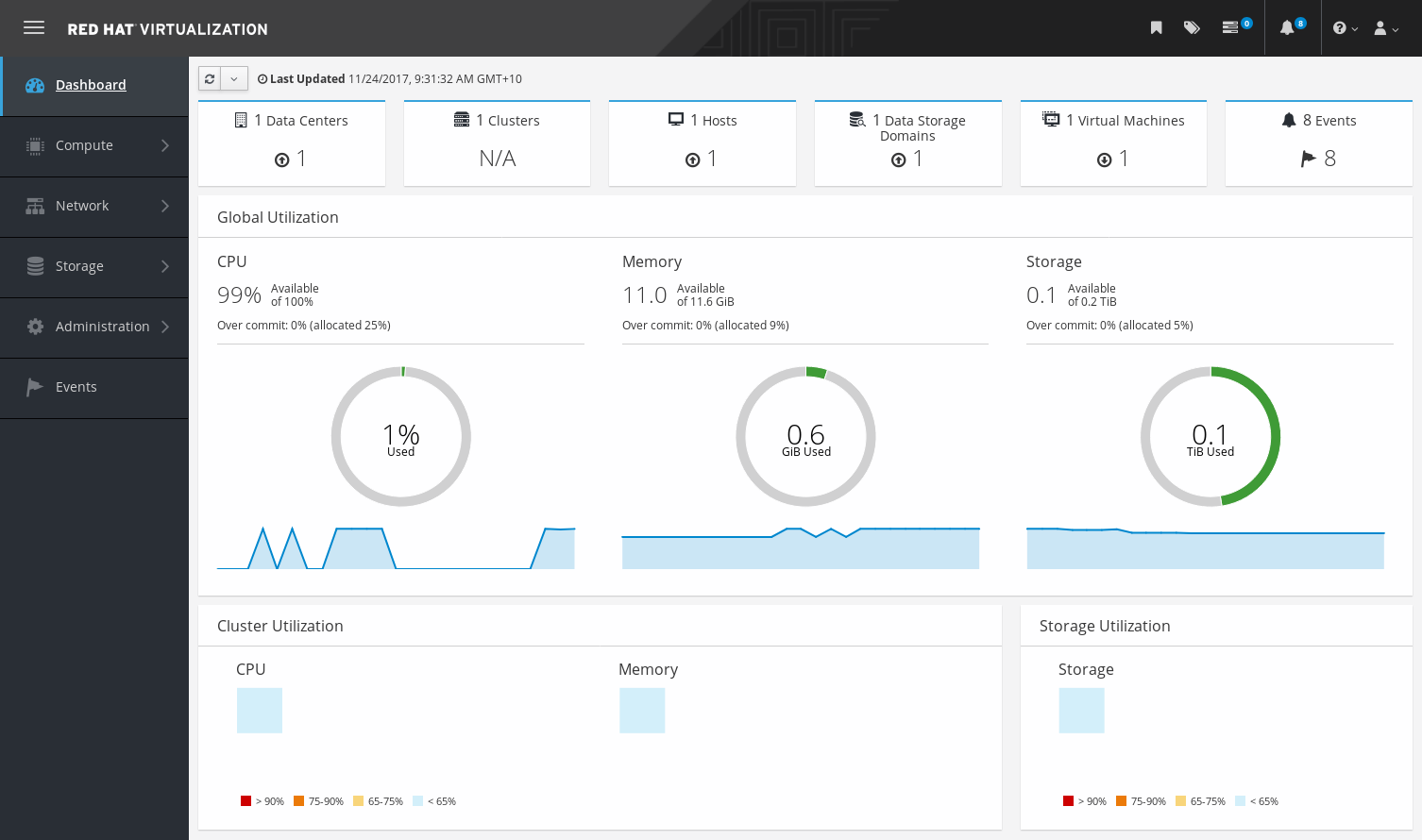
1.2. Dashboard
The Dashboard provides an overview of the oVirt system status by displaying a summary of oVirt’s resources and utilization. This summary can alert you to a problem and allows you to analyze the problem area.
The information in the dashboard is updated every 15 minutes by default from Data Warehouse, and every 15 seconds by default by the Engine API, or whenever the Dashboard is refreshed. The Dashboard is refreshed when the user changes back from another page or when manually refreshed. The Dashboard does not automatically refresh. The inventory card information is supplied by the Engine API and the utilization information is supplied by Data Warehouse. The Dashboard is implemented as a UI plugin component, which is automatically installed and upgraded alongside the Engine.
1.2.1. Prerequisites
The Dashboard requires that Data Warehouse is installed and configured. See Installing and Configuring Data Warehouse in the Data Warehouse Guide.
1.2.2. Global Inventory
The top section of the Dashboard provides a global inventory of the oVirt resources and includes items for data centers, clusters, hosts, storage domains, virtual machines, and events. Icons show the status of each resource and numbers show the quantity of the each resource with that status.

The title shows the number of a type of resource and their status is displayed below the title. Clicking on the resource title navigates to the related page in the oVirt Engine. The status for Clusters is always displayed as N/A.
| Icon | Status |
|---|---|
|
None of that resource added to oVirt. |
|
Shows the number of a resource with a warning status. Clicking on the icon navigates to the appropriate page with the search limited to that resource with a warning status. The search is limited differently for each resource:
|
|
Shows the number of a resource with an up status. Clicking on the icon navigates to the appropriate page with the search limited to resources that are up. |
|
Shows the number of a resource with a down status. Clicking on the icon navigates to the appropriate page with the search limited to resources with a down status. The search is limited differently for each resource:
|
images:images/Dashboard_Alert.png[title="Alert icon"] |
Shows the number of events with an alert status. Clicking on the icon navigates to Events with the search limited to events with the severity of alert. |
images:images/Dashboard_Error.png[title="Error icon"] |
Shows the number of events with an error status. Clicking on the icon navigates to Events with the search limited to events with the severity of error. |


1.2.3. Global Utilization
The Global Utilization section shows the system utilization of the CPU, Memory and Storage.
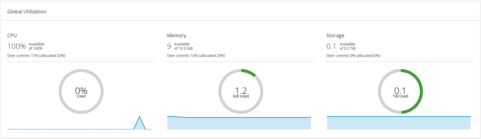
-
The top section shows the percentage of the available CPU, memory or storage and the over commit ratio. For example, the over commit ratio for the CPU is calculated by dividing the number of virtual cores by the number of physical cores that are available for the running virtual machines based on the latest data in Data Warehouse.
-
The donut displays the usage in percentage for the CPU, memory or storage and shows the average usage for all hosts based on the average usage in the last 5 minutes. Hovering over a section of the donut will display the value of the selected section.
-
The line graph at the bottom displays the trend in the last 24 hours. Each data point shows the average usage for a specific hour. Hovering over a point on the graph displays the time and the percentage used for the CPU graph and the amount of usage for the memory and storage graphs.
Top Utilized Resources
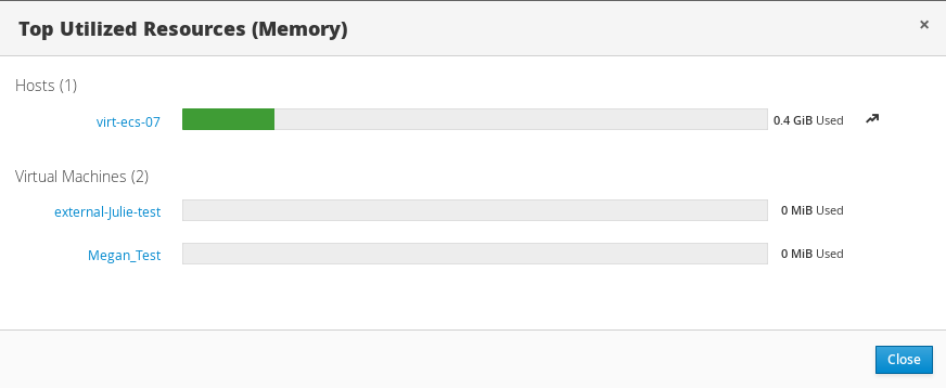
Clicking the donut in the global utilization section of the Dashboard will display a list of the top utilized resources for the CPU, memory or storage. For CPU and memory the pop-up shows a list of the ten hosts and virtual machines with the highest usage. For storage the pop-up shows a list of the top ten utilized storage domains and virtual machines. The arrow to the right of the usage bar shows the trend of usage for that resource in the last minute.
1.2.4. Cluster Utilization
The Cluster Utilization section shows the cluster utilization for the CPU and memory in a heatmap.

CPU
The heatmap of the CPU utilization for a specific cluster that shows the average utilization of the CPU for the last 24 hours. Hovering over the heatmap displays the cluster name. Clicking on the heatmap navigates to and displays the results of a search on a specific cluster sorted by CPU utilization. The formula used to calculate the usage of the CPU by the cluster is the average host CPU utilization in the cluster. This is calculated by using the average host CPU utilization for each host over the last 24 hours to find the total average usage of the CPU by the cluster.
Memory
The heatmap of the memory utilization for a specific cluster that shows the average utilization of the memory for the last 24 hours. Hovering over the heatmap displays the cluster name. Clicking on the heatmap navigates to and displays the results of a search on a specific cluster sorted by memory usage. The formula used to calculate the memory usage by the cluster is the total utilization of the memory in the cluster in GB. This is calculated by using the average host memory utilization for each host over the last 24 hours to find the total average usage of memory by the cluster.
1.2.5. Storage Utilization
The Storage Utilization section shows the storage utilization in a heatmap.

The heatmap shows the average utilization of the storage for the last 24 hours. The formula used to calculate the storage usage by the cluster is the total utilization of the storage in the cluster. This is calculated by using the average storage utilization for each host over the last 24 hours to find the total average usage of the storage by the cluster. Hovering over the heatmap displays the storage domain name. Clicking on the heatmap navigates to with the storage domains sorted by utilization.
1.3. Searches
1.3.1. Performing Searches in oVirt
The Administration Portal allows you to manage thousands of resources, such as virtual machines, hosts, users, and more. To perform a search, enter the search query (free-text or syntax-based) into the search bar, available on the main page for each resource. Search queries can be saved as bookmarks for future reuse, so you do not have to reenter a search query each time the specific search results are required. Searches are not case sensitive.
1.3.2. Search Syntax and Examples
The syntax of the search queries for oVirt resources is as follows:
result type: {criteria} [sortby sort_spec]
Syntax Examples
The following examples describe how the search query is used and help you to understand how oVirt assists with building search queries.
| Example | Result |
|---|---|
Hosts: Vms.status = up page 2 |
Displays page 2 of a list of all hosts running virtual machines that are up. |
Vms: domain = qa.company.com |
Displays a list of all virtual machines running on the specified domain. |
Vms: users.name = Mary |
Displays a list of all virtual machines belonging to users with the user name Mary. |
Events: severity > normal sortby time |
Displays the list of all Events whose severity is higher than Normal, sorted by time. |
1.3.3. Search Auto-Completion
The Administration Portal provides auto-completion to help you create valid and powerful search queries. As you type each part of a search query, a drop-down list of choices for the next part of the search opens below the Search Bar. You can either select from the list and then continue typing/selecting the next part of the search, or ignore the options and continue entering your query manually.
The following table specifies by example how the Administration Portal auto-completion assists in constructing a query:
Hosts: Vms.status = down
| Input | List Items Displayed | Action |
|---|---|---|
h |
|
Select |
Hosts: |
All host properties |
Type v |
Hosts: v |
host properties starting with a |
Select |
Hosts: Vms |
All virtual machine properties |
Type s |
Hosts: Vms.s |
All virtual machine properties beginning with |
Select |
Hosts: Vms.status |
|
Select or type = |
Hosts: Vms.status = |
All status values |
Select or type down |
1.3.4. Search Result Type Options
The result type allows you to search for resources of any of the following types:
-
Vms for a list of virtual machines
-
Host for a list of hosts
-
Pools for a list of pools
-
Template for a list of templates
-
Events for a list of events
-
Users for a list of users
-
Cluster for a list of clusters
-
DataCenter for a list of data centers
-
Storage for a list of storage domains
As each type of resource has a unique set of properties and a set of other resource types that it is associated with, each search type has a set of valid syntax combinations. You can also use the auto-complete feature to create valid queries easily.
1.3.5. Search Criteria
You can specify the search criteria after the colon in the query. The syntax of {criteria} is as follows:
<prop><operator><value>
or
<obj-type><prop><operator><value>
Examples
The following table describes the parts of the syntax:
| Part | Description | Values | Example | Note |
|---|---|---|---|---|
prop |
The property of the searched-for resource. Can also be the property of a resource type (see |
Limit your search to objects with a certain property. For example, search for objects with a status property. |
Status |
N/A |
obj-type |
A resource type that can be associated with the searched-for resource. |
These are system objects, like data centers and virtual machines. |
Users |
N/A |
operator |
Comparison operators. |
= != (not equal) > < >= <= |
N/A |
Value options depend on property. |
Value |
What the expression is being compared to. |
String Integer Ranking Date (formatted according to Regional Settings) |
Jones 256 normal |
|
1.3.6. Search: Multiple Criteria and Wildcards
Wildcards can be used in the <value> part of the syntax for strings. For example, to find all users beginning with m, enter m*.
You can perform a search having two criteria by using the Boolean operators AND and OR. For example:
Vms: users.name = m* AND status = Up
This query returns all running virtual machines for users whose names begin with "m".
Vms: users.name = m* AND tag = "paris-loc"
This query returns all virtual machines tagged with "paris-loc" for users whose names begin with "m".
When two criteria are specified without AND or OR, AND is implied. AND precedes OR, and OR precedes implied AND.
1.3.7. Search: Determining Search Order
You can determine the sort order of the returned information by using sortby. Sort direction (asc for ascending, desc for descending) can be included.
For example:
events: severity > normal sortby time desc
This query returns all Events whose severity is higher than Normal, sorted by time (descending order).
1.3.8. Searching for Data Centers
The following table describes all search options for Data Centers.
| Property (of resource or resource-type) | Type | Description (Reference) |
|---|---|---|
|
Depends on property type |
The property of the clusters associated with the data center. |
|
String |
The name of the data center. |
|
String |
A description of the data center. |
|
String |
The type of data center. |
|
List |
The availability of the data center. |
|
List |
Sorts the returned results by one of the resource properties. |
|
Integer |
The page number of results to display. |
Example
Datacenter: type = nfs and status != up
This example returns a list of data centers with a storage type of NFS and status other than up.
1.3.9. Searching for Clusters
The following table describes all search options for clusters.
| Property (of resource or resource-type) | Type | Description (Reference) |
|---|---|---|
|
Depends on property type |
The property of the data center associated with the cluster. |
|
String |
The data center to which the cluster belongs. |
|
String |
The unique name that identifies the clusters on the network. |
|
String |
The description of the cluster. |
|
String |
True or False indicating the status of the cluster. |
|
List |
Sorts the returned results by one of the resource properties. |
|
Integer |
The page number of results to display. |
Example
Clusters: initialized = true or name = Default
This example returns a list of clusters which are initialized or named Default.
1.3.10. Searching for Hosts
The following table describes all search options for hosts.
| Property (of resource or resource-type) | Type | Description (Reference) |
|---|---|---|
|
Depends on property type |
The property of the virtual machines associated with the host. |
|
Depends on property type |
The property of the templates associated with the host. |
|
Depends on property type |
The property of the events associated with the host. |
|
Depends on property type |
The property of the users associated with the host. |
|
String |
The name of the host. |
|
List |
The availability of the host. |
|
String |
The health status of the host as reported by external systems and plug-ins. |
|
String |
The cluster to which the host belongs. |
|
String |
The unique name that identifies the host on the network. |
|
Integer |
The percent of processing power used. |
|
Integer |
The percentage of memory used. |
|
Integer |
The percentage of network usage. |
|
Integer |
Jobs waiting to be executed in the run-queue per processor, in a given time slice. |
|
Integer |
The version number of the operating system. |
|
Integer |
The number of CPUs on the host. |
|
Integer |
The amount of memory available. |
|
Integer |
The processing speed of the CPU. |
|
String |
The type of CPU. |
|
Integer |
The number of virtual machines currently running. |
|
Integer |
The number of virtual machines currently being migrated. |
|
Integer |
The percentage of committed memory. |
|
String |
The tag assigned to the host. |
|
String |
The type of host. |
|
String |
The data center to which the host belongs. |
|
List |
Sorts the returned results by one of the resource properties. |
|
Integer |
The page number of results to display. |
Example
Hosts: cluster = Default and Vms.os = rhel6
This example returns a list of hosts which are part of the Default cluster and host virtual machines running the Enterprise Linux 6 operating system.
1.3.11. Searching for Networks
The following table describes all search options for networks.
| Property (of resource or resource-type) | Type | Description (Reference) |
|---|---|---|
|
Depends on property type |
The property of the cluster associated with the network. |
|
Depends on property type |
The property of the host associated with the network. |
|
String |
The human readable name that identifies the network. |
|
String |
Keywords or text describing the network, optionally used when creating the network. |
|
Integer |
The VLAN ID of the network. |
|
String |
Whether Spanning Tree Protocol (STP) is enabled or disabled for the network. |
|
Integer |
The maximum transmission unit for the logical network. |
|
String |
Whether the network is only used for virtual machine traffic. |
|
String |
The data center to which the network is attached. |
|
List |
Sorts the returned results by one of the resource properties. |
|
Integer |
The page number of results to display. |
Example
Network: mtu > 1500 and vmnetwork = true
This example returns a list of networks with a maximum transmission unit greater than 1500 bytes, and which are set up for use by only virtual machines.
1.3.12. Searching for Storage
The following table describes all search options for storage.
| Property (of resource or resource-type) | Type | Description (Reference) |
|---|---|---|
|
Depends on property type |
The property of the hosts associated with the storage. |
|
Depends on property type |
The property of the clusters associated with the storage. |
|
String |
The unique name that identifies the storage on the network. |
|
String |
The status of the storage domain. |
|
String |
The health status of the storage domain as reported by external systems and plug-ins. |
|
String |
The data center to which the storage belongs. |
|
String |
The type of the storage. |
|
Integer |
The size (GB) of the free storage. |
|
Integer |
The amount (GB) of the storage that is used. |
|
Integer |
The total amount (GB) of the storage that is available. |
|
Integer |
The amount (GB) of the storage that is committed. |
|
List |
Sorts the returned results by one of the resource properties. |
|
Integer |
The page number of results to display. |
Example
Storage: free_size > 6 GB and total_size < 20 GB
This example returns a list of storage with free storage space greater than 6 GB, or total storage space less than 20 GB.
1.3.13. Searching for Disks
The following table describes all search options for disks.
You can use the Disk Type and Content Type filtering options to reduce the number of displayed virtual disks.
|
| Property (of resource or resource-type) | Type | Description (Reference) |
|---|---|---|
|
Depends on property type |
The property of the data centers associated with the disk. |
|
Depends on property type |
The property of the storage associated with the disk. |
|
String |
The human readable name that identifies the storage on the network. |
|
String |
Keywords or text describing the disk, optionally used when creating the disk. |
|
Integer |
The virtual size of the disk. |
|
Integer |
The size of the disk. |
|
Integer |
The actual size allocated to the disk. |
|
Integer |
The date the disk was created. |
|
String |
Whether the disk can or cannot be booted. Valid values are one of |
|
String |
Whether the disk can or cannot be attached to more than one virtual machine at a time. Valid values are one of |
|
String |
The format of the disk. Can be one of |
|
String |
The status of the disk. Can be one of |
|
String |
The type of the disk. Can be one of |
|
Integer |
The number of virtual machine(s) to which the disk is attached. |
|
String |
The name(s) of the virtual machine(s) to which the disk is attached. |
|
String |
The name of the quota enforced on the virtual disk. |
|
List |
Sorts the returned results by one of the resource properties. |
|
Integer |
The page number of results to display. |
Example
Disks: format = cow and provisioned_size > 8
This example returns a list of virtual disks with QCOW format and an allocated disk size greater than 8 GB.
1.3.14. Searching for Volumes
The following table describes all search options for volumes.
| Property (of resource or resource-type) | Type | Description (Reference) |
|---|---|---|
|
String |
The name of the cluster associated with the volume. |
|
Depends on property type (examples: name, description, comment, architecture) |
The property of the clusters associated with the volume. |
|
String |
The human readable name that identifies the volume. |
|
String |
Can be one of distribute, replicate, distributed_replicate, stripe, or distributed_stripe. |
|
Integer |
Can be one of TCP or RDMA. |
|
Integer |
Number of replica. |
|
Integer |
Number of stripes. |
|
String |
The status of the volume. Can be one of Up or Down. |
|
List |
Sorts the returned results by one of the resource properties. |
|
Integer |
The page number of results to display. |
Example
Volume: transport_type = rdma and stripe_count >= 2
This example returns a list of volumes with transport type set to RDMA, and with 2 or more stripes.
1.3.15. Searching for Virtual Machines
The following table describes all search options for virtual machines.
|
Currently, the Network Label, Custom Emulated Machine, and Custom CPU Type properties are not supported search parameters. |
| Property (of resource or resource-type) | Type | Description (Reference) |
|---|---|---|
|
Depends on property type |
The property of the hosts associated with the virtual machine. |
|
Depends on property type |
The property of the templates associated with the virtual machine. |
|
Depends on property type |
The property of the events associated with the virtual machine. |
|
Depends on property type |
The property of the users associated with the virtual machine. |
|
Depends on the property type |
The property of storage devices associated with the virtual machine. |
|
Depends on the property type |
The property of the vNIC associated with the virtual machine. |
|
String |
The name of the virtual machine. |
|
List |
The availability of the virtual machine. |
|
Integer |
The IP address of the virtual machine. |
|
Integer |
The number of minutes that the virtual machine has been running. |
|
String |
The domain (usually Active Directory domain) that groups these machines. |
|
String |
The operating system selected when the virtual machine was created. |
|
Date |
The date on which the virtual machine was created. |
|
String |
The unique name that identifies the virtual machine on the network. |
|
Integer |
The percent of processing power used. |
|
Integer |
The percentage of memory used. |
|
Integer |
The percentage of network used. |
|
Integer |
The maximum memory defined. |
|
String |
The applications currently installed on the virtual machine. |
|
List |
The cluster to which the virtual machine belongs. |
|
List |
The virtual machine pool to which the virtual machine belongs. |
|
String |
The name of the user currently logged in to the virtual machine. |
|
List |
The tags to which the virtual machine belongs. |
|
String |
The data center to which the virtual machine belongs. |
|
List |
The virtual machine type (server or desktop). |
|
String |
The name of the quota associated with the virtual machine. |
|
String |
Keywords or text describing the virtual machine, optionally used when creating the virtual machine. |
|
List |
Sorts the returned results by one of the resource properties. |
|
Integer |
The page number of results to display. |
|
Boolean |
The virtual machine has pending configuration changes. |
Example
Vms: template.name = Win* and user.name = ""
This example returns a list of virtual machines whose base template name begins with Win and are assigned to any user.
Example
Vms: cluster = Default and os = windows7
This example returns a list of virtual machines that belong to the Default cluster and are running Windows 7.
1.3.16. Searching for Pools
The following table describes all search options for Pools.
| Property (of resource or resource-type) | Type | Description (Reference) |
|---|---|---|
|
String |
The name of the pool. |
|
String |
The description of the pool. |
|
List |
The type of pool. |
|
List |
Sorts the returned results by one of the resource properties. |
|
Integer |
The page number of results to display. |
Example
Pools: type = automatic
This example returns a list of pools with a type of automatic.
1.3.17. Searching for Templates
The following table describes all search options for templates.
| Property (of resource or resource-type) | Type | Description (Reference) |
|---|---|---|
|
String |
The property of the virtual machines associated with the template. |
|
String |
The property of the hosts associated with the template. |
|
String |
The property of the events associated with the template. |
|
String |
The property of the users associated with the template. |
|
String |
The name of the template. |
|
String |
The domain of the template. |
|
String |
The type of operating system. |
|
Integer |
The date on which the template was created. Date format is mm/dd/yy. |
|
Integer |
The number of virtual machines created from the template. |
|
Integer |
Defined memory. |
|
String |
The description of the template. |
|
String |
The status of the template. |
|
String |
The cluster associated with the template. |
|
String |
The data center associated with the template. |
|
String |
The quota associated with the template. |
|
List |
Sorts the returned results by one of the resource properties. |
|
Integer |
The page number of results to display. |
Example
Template: Events.severity >= normal and Vms.uptime > 0
This example returns a list of templates where events of normal or greater severity have occurred on virtual machines derived from the template, and the virtual machines are still running.
1.3.18. Searching for Users
The following table describes all search options for users.
| Property (of resource or resource-type) | Type | Description (Reference) |
|---|---|---|
|
Depends on property type |
The property of the virtual machines associated with the user. |
|
Depends on property type |
The property of the hosts associated with the user. |
|
Depends on property type |
The property of the templates associated with the user. |
|
Depends on property type |
The property of the events associated with the user. |
|
String |
The name of the user. |
|
String |
The last name of the user. |
|
String |
The unique name of the user. |
|
String |
The department to which the user belongs. |
|
String |
The group to which the user belongs. |
|
String |
The title of the user. |
|
String |
The status of the user. |
|
String |
The role of the user. |
|
String |
The tag to which the user belongs. |
|
String |
The pool to which the user belongs. |
|
List |
Sorts the returned results by one of the resource properties. |
|
Integer |
The page number of results to display. |
Example
Users: Events.severity > normal and Vms.status = up or Vms.status = pause
This example returns a list of users where events of greater than normal severity have occurred on their virtual machines AND the virtual machines are still running; or the users' virtual machines are paused.
1.3.19. Searching for Events
The following table describes all search options you can use to search for events. Auto-completion is offered for many options as appropriate.
| Property (of resource or resource-type) | Type | Description (Reference) |
|---|---|---|
|
Depends on property type |
The property of the virtual machines associated with the event. |
|
Depends on property type |
The property of the hosts associated with the event. |
|
Depends on property type |
The property of the templates associated with the event. |
|
Depends on property type |
The property of the users associated with the event. |
|
Depends on property type |
The property of the clusters associated with the event. |
|
Depends on property type |
The property of the volumes associated with the event. |
|
List |
Type of the event. |
|
List |
The severity of the event: Warning/Error/Normal. |
|
String |
Description of the event type. |
|
List |
Day the event occurred. |
|
String |
The user name associated with the event. |
|
String |
The host associated with the event. |
|
String |
The virtual machine associated with the event. |
|
String |
The template associated with the event. |
|
String |
The storage associated with the event. |
|
String |
The data center associated with the event. |
|
String |
The volume associated with the event. |
|
Integer |
The identification number of the event. |
|
List |
Sorts the returned results by one of the resource properties. |
|
Integer |
The page number of results to display. |
Example
Events: Vms.name = testdesktop and Hosts.name = gonzo.example.com
This example returns a list of events, where the event occurred on the virtual machine named testdesktop while it was running on the host gonzo.example.com.
1.4. Bookmarks
1.4.1. Saving a Query String as a Bookmark
A bookmark can be used to remember a search query, and shared with other users.
-
Enter the desired search query in the search bar and perform the search.
-
Click the star-shaped Bookmark button to the right of the search bar. This opens the New Bookmark window.
-
Enter the Name of the bookmark.
-
Edit the Search string field, if required.
-
Click OK.
Click the Bookmarks icon ( ) in the header bar to find and select the bookmark.
1.4.2. Editing a Bookmark
You can modify the name and search string of a bookmark.
-
Click the Bookmarks icon (
) in the header bar. -
Select a bookmark and click Edit.
-
Change the Name and Search string fields as necessary.
-
Click OK.
1.4.3. Deleting a Bookmark
When a bookmark is no longer needed, remove it.
-
Click the Bookmarks icon (
) in the header bar. -
Select a bookmark and click Remove.
-
Click OK.
1.5. Tags
1.5.1. Using Tags to Customize Interactions with oVirt
After your oVirt platform is set up and configured to your requirements, you can customize the way you work with it using tags. Tags allow system resources to be arranged into groups or categories. This is useful when many objects exist in the virtualization environment and the administrator wants to concentrate on a specific set of them.
This section describes how to create and edit tags, assign them to hosts or virtual machines and search using the tags as criteria. Tags can be arranged in a hierarchy that matches a structure, to fit the needs of the enterprise.
To create, modify, and remove Administration Portal tags, click the Tags icon ( ) in the header bar.
1.5.2. Creating a Tag
Create tags so you can filter search results using tags.
-
Click the Tags icon (
) in the header bar. -
Click Add to create a new tag, or select a tag and click New to create a descendant tag.
-
Enter the Name and Description of the new tag.
-
Click OK.
1.5.3. Modifying a Tag
You can edit the name and description of a tag.
Modifying a Tag
-
Click the Tags icon (
) in the header bar. -
Select the tag you want to modify and click Edit.
-
Change the Name and Description fields as necessary.
-
Click OK.
1.5.4. Deleting a Tag
When a tag is no longer needed, remove it.
-
Click the Tags icon (
) in the header bar. -
Select the tag you want to delete and click Remove. A message warns you that removing the tag will also remove all descendants of the tag.
-
Click OK.
You have removed the tag and all its descendants. The tag is also removed from all the objects that it was attached to.
1.5.5. Adding and Removing Tags to and from Objects
You can assign tags to and remove tags from hosts, virtual machines, and users.
-
Select the object(s) you want to tag or untag.
-
Click More Actions (
 ), then click Assign Tags.
 -
Select the check box to assign a tag to the object, or clear the check box to detach the tag from the object.
-
Click OK.
The specified tag is now added or removed as a custom property of the selected object(s).
1.5.6. Searching for Objects Using Tags
Enter a search query using tag as the property and the desired value or set of values as criteria for the search.
The objects tagged with the specified criteria are listed in the results list.
|
If you search for objects using |
1.5.7. Customizing Hosts with Tags
You can use tags to store information about your hosts. You can then search for hosts based on tags. For more information on searches, see Searches.
-
Click and select a host.
-
Click More Actions (
), then click Assign Tags. -
Select the check boxes of applicable tags.
-
Click OK.
You have added extra, searchable information about your host as tags.
2. Administering the Resources
2.1. Quality of Service
oVirt allows you to define quality of service entries that provide fine-grained control over the level of input and output, processing, and networking capabilities that resources in your environment can access. Quality of service entries are defined at the data center level and are assigned to profiles created under clusters and storage domains. These profiles are then assigned to individual resources in the clusters and storage domains where the profiles were created.
2.1.1. Storage Quality of Service
Storage quality of service defines the maximum level of throughput and the maximum level of input and output operations for a virtual disk in a storage domain. Assigning storage quality of service to a virtual disk allows you to fine tune the performance of storage domains and prevent the storage operations associated with one virtual disk from affecting the storage capabilities available to other virtual disks hosted in the same storage domain.
Creating a Storage Quality of Service Entry
-
Click .
-
Click a data center’s name. This opens the details view.
-
Click the QoS tab.
-
Under Storage, click New.
-
Enter a QoS Name and a Description for the quality of service entry.
-
Specify the Throughput quality of service by clicking one of the radio buttons:
-
None
-
Total - Enter the maximum permitted total throughput in the MB/s field.
-
Read/Write - Enter the maximum permitted throughput for read operations in the left MB/s field, and the maximum permitted throughput for write operations in the right MB/s field.
-
-
Specify the input and output (IOps) quality of service by clicking one of the radio buttons:
-
None
-
Total - Enter the maximum permitted number of input and output operations per second in the IOps field.
-
Read/Write - Enter the maximum permitted number of input operations per second in the left IOps field, and the maximum permitted number of output operations per second in the right IOps field.
-
-
Click OK.
You have created a storage quality of service entry, and can create disk profiles based on that entry in data storage domains that belong to the data center.
Removing a Storage Quality of Service Entry
Remove an existing storage quality of service entry.
-
Click .
-
Click a data center’s name. This opens the details view.
-
Click the QoS tab.
-
Under Storage, select a storage quality of service entry and click Remove.
-
Click OK.
If any disk profiles were based on that entry, the storage quality of service entry for those profiles is automatically set to [unlimited].
2.1.2. Virtual Machine Network Quality of Service
Virtual machine network quality of service is a feature that allows you to create profiles for limiting both the inbound and outbound traffic of individual virtual network interface controllers. With this feature, you can limit bandwidth in a number of layers, controlling the consumption of network resources.
Creating a Virtual Machine Network Quality of Service Entry
Create a virtual machine network quality of service entry to regulate network traffic when applied to a virtual network interface controller (vNIC) profile, also known as a virtual machine network interface profile.
Creating a Virtual Machine Network Quality of Service Entry
-
Click .
-
Click a data center’s name. This opens the details view.
-
Click the QoS tab.
-
Under VM Network, click New.
-
Enter a Name for the virtual machine network quality of service entry.
-
Enter the limits for the Inbound and Outbound network traffic.
-
Click OK.
You have created a virtual machine network quality of service entry that can be used in a virtual network interface controller.
Settings in the New Virtual Machine Network QoS and Edit Virtual Machine Network QoS Windows Explained
Virtual machine network quality of service settings allow you to configure bandwidth limits for both inbound and outbound traffic on three distinct levels.
| Field Name | Description |
|---|---|
Data Center |
The data center to which the virtual machine network QoS policy is to be added. This field is configured automatically according to the selected data center. |
Name |
A name to represent the virtual machine network QoS policy within the Engine. |
Inbound |
The settings to be applied to inbound traffic. Select or clear the Inbound check box to enable or disable these settings.
|
Outbound |
The settings to be applied to outbound traffic. Select or clear the Outbound check box to enable or disable these settings.
|
To change the maximum value allowed by the Average, Peak, or Burst fields, use the engine-config command to change the value of the MaxAverageNetworkQoSValue, MaxPeakNetworkQoSValue, or MaxBurstNetworkQoSValue configuration keys. You must restart the ovirt-engine service for any changes to take effect. For example:
# engine-config -s MaxAverageNetworkQoSValue=2048
# systemctl restart ovirt-engine
Removing a Virtual Machine Network Quality of Service Entry
Remove an existing virtual machine network quality of service entry.
-
Click .
-
Click a data center’s name. This opens the details view.
-
Click the QoS tab.
-
Under VM Network, select a virtual machine network quality of service entry and click Remove.
-
Click OK.
2.1.3. Host Network Quality of Service
Host network quality of service configures the networks on a host to enable the control of network traffic through the physical interfaces. Host network quality of service allows for the fine tuning of network performance by controlling the consumption of network resources on the same physical network interface controller. This helps to prevent situations where one network causes other networks attached to the same physical network interface controller to no longer function due to heavy traffic. By configuring host network quality of service, these networks can now function on the same physical network interface controller without congestion issues.
Creating a Host Network Quality of Service Entry
Create a host network quality of service entry.
-
Click .
-
Click a data center’s name. This opens the details view.
-
Click the QoS tab.
-
Under Host Network, click New.
-
Enter a Qos Name and a description for the quality of service entry.
-
Enter the desired values for Weighted Share, Rate Limit [Mbps], and Committed Rate [Mbps].
-
Click OK.
Settings in the New Host Network Quality of Service and Edit Host Network Quality of Service Windows Explained
Host network quality of service settings allow you to configure bandwidth limits for outbound traffic.
| Field Name | Description |
|---|---|
Data Center |
The data center to which the host network QoS policy is to be added. This field is configured automatically according to the selected data center. |
QoS Name |
A name to represent the host network QoS policy within the Engine. |
Description |
A description of the host network QoS policy. |
Outbound |
The settings to be applied to outbound traffic.
|
To change the maximum value allowed by the Rate Limit [Mbps] or Committed Rate [Mbps] fields, use the engine-config command to change the value of the MaxAverageNetworkQoSValue configuration key. You must restart the ovirt-engine service for the change to take effect. For example:
# engine-config -s MaxAverageNetworkQoSValue=2048
# systemctl restart ovirt-engine
Removing a Host Network Quality of Service Entry
Remove an existing network quality of service entry.
-
Click .
-
Click a data center’s name. This opens the details view.
-
Click the QoS tab.
-
Under Host Network, select a host network quality of service entry and click Remove.
-
Click OK when prompted.
2.1.4. CPU Quality of Service
CPU quality of service defines the maximum amount of processing capability a virtual machine can access on the host on which it runs, expressed as a percent of the total processing capability available to that host. Assigning CPU quality of service to a virtual machine allows you to prevent the workload on one virtual machine in a cluster from affecting the processing resources available to other virtual machines in that cluster.
Creating a CPU Quality of Service Entry
Create a CPU quality of service entry.
-
Click .
-
Click a data center’s name. This opens the details view.
-
Click the QoS tab.
-
Under CPU, click New.
-
Enter a QoS Name and a Description for the quality of service entry.
-
Enter the maximum processing capability the quality of service entry permits in the Limit (%) field. Do not include the
%symbol. -
Click OK.
You have created a CPU quality of service entry, and can create CPU profiles based on that entry in clusters that belong to the data center.
Removing a CPU Quality of Service Entry
Remove an existing CPU quality of service entry.
-
Click .
-
Click a data center’s name. This opens the details view.
-
Click the QoS tab.
-
Under CPU, select a CPU quality of service entry and click Remove.
-
Click OK.
If any CPU profiles were based on that entry, the CPU quality of service entry for those profiles is automatically set to [unlimited].
2.2. Data Centers
2.2.1. Introduction to Data Centers
A data center is a logical entity that defines the set of resources used in a specific environment. A data center is considered a container resource, in that it is comprised of logical resources, in the form of clusters and hosts; network resources, in the form of logical networks and physical NICs; and storage resources, in the form of storage domains.
A data center can contain multiple clusters, which can contain multiple hosts; it can have multiple storage domains associated to it; and it can support multiple virtual machines on each of its hosts. A oVirt environment can contain multiple data centers; the data center infrastructure allows you to keep these centers separate.
All data centers are managed from the single Administration Portal.
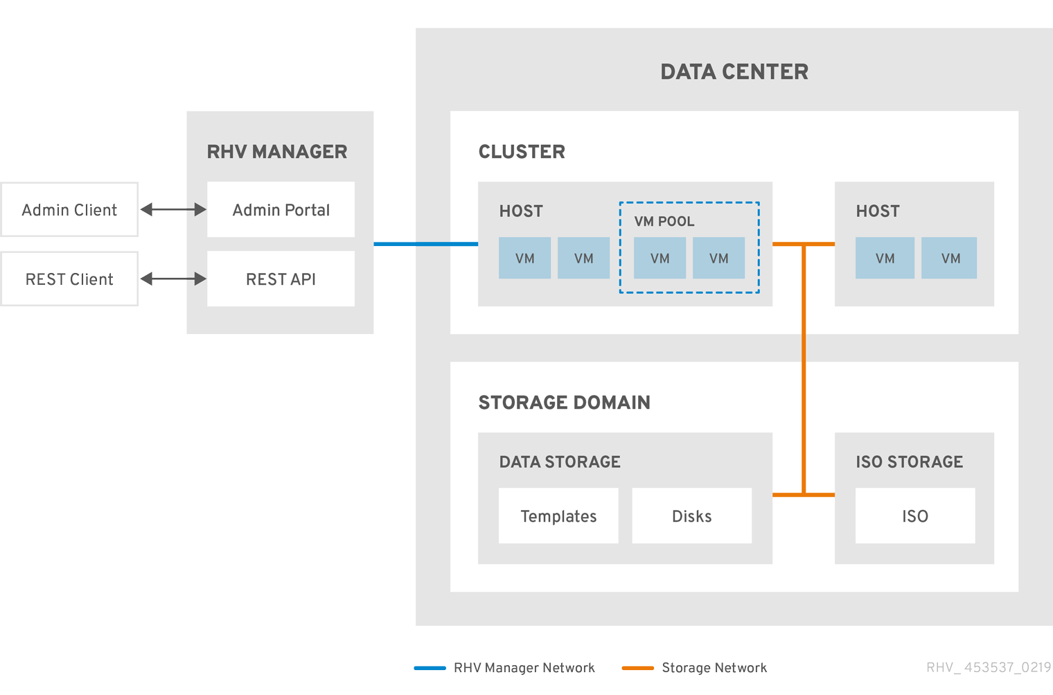
oVirt creates a default data center during installation. You can configure the default data center, or set up new appropriately named data centers.
2.2.2. The Storage Pool Manager
The Storage Pool Manager (SPM) is a role given to one of the hosts in the data center enabling it to manage the storage domains of the data center. The SPM entity can be run on any host in the data center; the oVirt Engine grants the role to one of the hosts. The SPM does not preclude the host from its standard operation; a host running as SPM can still host virtual resources.
The SPM entity controls access to storage by coordinating the metadata across the storage domains. This includes creating, deleting, and manipulating virtual disks (images), snapshots, and templates, and allocating storage for sparse block devices (on SAN). This is an exclusive responsibility: only one host can be the SPM in the data center at one time to ensure metadata integrity.
The oVirt Engine ensures that the SPM is always available. The Engine moves the SPM role to a different host if the SPM host encounters problems accessing the storage. When the SPM starts, it ensures that it is the only host granted the role; therefore it will acquire a storage-centric lease. This process can take some time.
2.2.3. SPM Priority
The SPM role uses some of a host’s available resources. The SPM priority setting of a host alters the likelihood of the host being assigned the SPM role: a host with high SPM priority will be assigned the SPM role before a host with low SPM priority. Critical virtual machines on hosts with low SPM priority will not have to contend with SPM operations for host resources.
You can change a host’s SPM priority in the SPM tab in the Edit Host window.
2.2.4. Data Center Tasks
Creating a New Data Center
This procedure creates a data center in your virtualization environment. The data center requires a functioning cluster, host, and storage domain to operate.
|
After you set the Compatibility Version, you cannot lower the version number. Version regression is not supported. You can specify a MAC pool range for a cluster. Setting a MAC pool range is no longer supported. |
-
Click .
-
Click New.
-
Enter the Name and Description of the data center.
-
Select the Storage Type, Compatibility Version, and Quota Mode of the data center from the drop-down menus.
-
Click OK to create the data center and open the Data Center - Guide Me window.
-
The Guide Me window lists the entities that need to be configured for the data center. Configure these entities or postpone configuration by clicking the Configure Later button. Configuration can be resumed by selecting the data center and clicking More Actions (
), then clicking Guide Me.
The new data center will remain Uninitialized until a cluster, host, and storage domain are configured for it; use Guide Me to configure these entities.
Explanation of Settings in the New Data Center and Edit Data Center Windows
The table below describes the settings of a data center as displayed in the New Data Center and Edit Data Center windows. Invalid entries are outlined in orange when you click OK, prohibiting the changes being accepted. In addition, field prompts indicate the expected values or range of values.
| Field | Description/Action |
|---|---|
Name |
The name of the data center. This text field has a 40-character limit and must be a unique name with any combination of uppercase and lowercase letters, numbers, hyphens, and underscores. |
Description |
The description of the data center. This field is recommended but not mandatory. |
Storage Type |
Choose Shared or Local storage type. Different types of storage domains (iSCSI, NFS, FC, POSIX, and Gluster) can be added to the same data center. Local and shared domains, however, cannot be mixed. You can change the storage type after the data center is initialized. See Changing the Data Center Storage Type. |
Compatibility Version |
The version of oVirt. After upgrading the oVirt Engine, the hosts, clusters and data centers may still be in the earlier version. Ensure that you have upgraded all the hosts, then the clusters, before you upgrade the Compatibility Level of the data center. |
Quota Mode |
Quota is a resource limitation tool provided with oVirt. Choose one of:
|
Comment |
Optionally add a plain text comment about the data center. |
Re-Initializing a Data Center: Recovery Procedure
This recovery procedure replaces the master data domain of your data center with a new master data domain. You must re-initialize your master data domain if its data is corrupted. Re-initializing a data center allows you to restore all other resources associated with the data center, including clusters, hosts, and non-problematic storage domains.
You can import any backup or exported virtual machines or templates into your new master data domain.
-
Click and select the data center.
-
Ensure that any storage domains attached to the data center are in maintenance mode.
-
Click More Actions (
), then click Re-Initialize Data Center. -
The Data Center Re-Initialize window lists all available (detached; in maintenance mode) storage domains. Click the radio button for the storage domain you are adding to the data center.
-
Select the Approve operation check box.
-
Click OK.
The storage domain is attached to the data center as the master data domain and activated. You can now import any backup or exported virtual machines or templates into your new master data domain.
Removing a Data Center
An active host is required to remove a data center. Removing a data center will not remove the associated resources.
-
Ensure the storage domains attached to the data center are in maintenance mode.
-
Click and select the data center to remove.
-
Click Remove.
-
Click OK.
Force Removing a Data Center
A data center becomes Non Responsive if the attached storage domain is corrupt or if the host becomes Non Responsive. You cannot Remove the data center under either circumstance.
Force Remove does not require an active host. It also permanently removes the attached storage domain.
It may be necessary to Destroy a corrupted storage domain before you can Force Remove the data center.
-
Click and select the data center to remove.
-
Click More Actions (
), then click Force Remove. -
Select the Approve operation check box.
-
Click OK
The data center and attached storage domain are permanently removed from the oVirt environment.
Changing the Data Center Storage Type
You can change the storage type of the data center after it has been initialized. This is useful for data domains that are used to move virtual machines or templates around.
Limitations
-
Shared to Local - For a data center that does not contain more than one host and more than one cluster, since a local data center does not support it.
-
Local to Shared - For a data center that does not contain a local storage domain.
-
Click and select the data center to change.
-
Click Edit.
-
Change the Storage Type to the desired value.
-
Click OK.
Changing the Data Center Compatibility Version
oVirt data centers have a compatibility version. The compatibility version indicates the version of oVirt with which the data center is intended to be compatible. All clusters in the data center must support the desired compatibility level.
-
To change the data center compatibility level, you must first update the compatibility version of all clusters and virtual machines in the data center.
-
In the Administration Portal, click .
-
Select the data center to change and click Edit.
-
Change the Compatibility Version to the desired value.
-
Click OK. The Change Data Center Compatibility Version confirmation dialog opens.
-
Click OK to confirm.
2.2.5. Data Centers and Storage Domains
Attaching an Existing Data Domain to a Data Center
Data domains that are Unattached can be attached to a data center. Shared storage domains of multiple types (iSCSI, NFS, FC, POSIX, and Gluster) can be added to the same data center.
-
Click .
-
Click a data center’s name. This opens the details view.
-
Click the Storage tab to list the storage domains already attached to the data center.
-
Click Attach Data.
-
Select the check box for the data domain to attach to the data center. You can select multiple check boxes to attach multiple data domains.
-
Click OK.
The data domain is attached to the data center and is automatically activated.
Attaching an Existing ISO domain to a Data Center
An ISO domain that is Unattached can be attached to a data center. The ISO domain must be of the same Storage Type as the data center.
Only one ISO domain can be attached to a data center.
-
Click .
-
Click a data center’s name. This opens the details view.
-
Click the Storage tab to list the storage domains already attached to the data center.
-
Click Attach ISO.
-
Click the radio button for the appropriate ISO domain.
-
Click OK.
The ISO domain is attached to the data center and is automatically activated.
Attaching an Existing Export Domain to a Data Center
|
The export storage domain is deprecated. Storage data domains can be unattached from a data center and imported to another data center in the same environment, or in a different environment. Virtual machines, floating virtual disks, and templates can then be uploaded from the imported storage domain to the attached data center. See Importing Existing Storage Domains for information on importing storage domains. |
An export domain that is Unattached can be attached to a data center. Only one export domain can be attached to a data center.
-
Click .
-
Click a data center’s name. This opens the details view.
-
Click the Storage tab to list the storage domains already attached to the data center.
-
Click Attach Export.
-
Click the radio button for the appropriate export domain.
-
Click OK.
The export domain is attached to the data center and is automatically activated.
Detaching a Storage Domain from a Data Center
Detaching a storage domain from a data center stops the data center from associating with that storage domain. The storage domain is not removed from the oVirt environment; it can be attached to another data center.
Data, such as virtual machines and templates, remains attached to the storage domain.
|
Although it possible to detach the last master storage domain, this is not recommended. If the master storage domain is detached, it must be reinitialized. If the storage domain is reinitialized, all your data will be lost, and the storage domain might not find your disks again. |
-
Click .
-
Click a data center’s name. This opens the details view.
-
Click the Storage tab to list the storage domains attached to the data center.
-
Select the storage domain to detach. If the storage domain is
Active, click Maintenance. -
Click OK to initiate maintenance mode.
-
Click Detach.
-
Click OK.
It can take up to several minutes for the storage domain to disappear from the details view.
2.3. Clusters
2.3.1. Introduction to Clusters
A cluster is a logical grouping of hosts that share the same storage domains and have the same type of CPU (either Intel or AMD). If the hosts have different generations of CPU models, they use only the features present in all models.
Each cluster in the system must belong to a data center, and each host in the system must belong to a cluster. Virtual machines are dynamically allocated to any host in a cluster and can be migrated between them, according to policies defined on the cluster and settings on the virtual machines. The cluster is the highest level at which power and load-sharing policies can be defined.
The number of hosts and number of virtual machines that belong to a cluster are displayed in the results list under Host Count and VM Count, respectively.
Clusters run virtual machines or Gluster Storage Servers. These two purposes are mutually exclusive: A single cluster cannot support virtualization and storage hosts together.
oVirt creates a default cluster in the default data center during installation.

2.3.2. Cluster Tasks
|
Some cluster options do not apply to Gluster clusters. For more information about using Gluster Storage with oVirt, see Configuring oVirt with Gluster Storage. |
Creating a New Cluster
A data center can contain multiple clusters, and a cluster can contain multiple hosts. All hosts in a cluster must have the same CPU architecture. To optimize your CPU types, create your hosts before you create your cluster. After creating the cluster, you can configure the hosts using the Guide Me button.
-
Click .
-
Click New.
-
Select the Data Center the cluster will belong to from the drop-down list.
-
Enter the Name and Description of the cluster.
-
Select a network from the Management Network drop-down list to assign the management network role.
-
Select the CPU Architecture.
-
For CPU Type, select the oldest CPU processor family among the hosts that will be part of this cluster. The CPU types are listed in order from the oldest to newest.
A hosts whose CPU processor family is older than the one you specify with CPU Type cannot be part of this cluster. For details, see Which CPU family should a RHEV3 or RHV4 cluster be set to?.
-
Select the FIPS Mode of the cluster from the drop-down list.
-
Select the Compatibility Version of the cluster from the drop-down list.
-
Select the Switch Type from the drop-down list.
-
Select the Firewall Type for hosts in the cluster, either Firewalld (default) or iptables.
iptables is only supported on Enterprise Linux 7 hosts, in clusters with compatibility version 4.2 or 4.3. You can only add Enterprise Linux 8 hosts to clusters with firewall type firewalld
-
Select either the Enable Virt Service or Enable Gluster Service check box to define whether the cluster will be populated with virtual machine hosts or with Gluster-enabled nodes.
-
Optionally select the Enable to set VM maintenance reason check box to enable an optional reason field when a virtual machine is shut down from the Engine, allowing the administrator to provide an explanation for the maintenance.
-
Optionally select the Enable to set Host maintenance reason check box to enable an optional reason field when a host is placed into maintenance mode from the Engine, allowing the administrator to provide an explanation for the maintenance.
-
Optionally select the /dev/hwrng source (external hardware device) check box to specify the random number generator device that all hosts in the cluster will use. The /dev/urandom source (Linux-provided device) is enabled by default.
-
Click the Optimization tab to select the memory page sharing threshold for the cluster, and optionally enable CPU thread handling and memory ballooning on the hosts in the cluster.
-
Click the Migration Policy tab to define the virtual machine migration policy for the cluster.
-
Click the Scheduling Policy tab to optionally configure a scheduling policy, configure scheduler optimization settings, enable trusted service for hosts in the cluster, enable HA Reservation, and select a serial number policy.
-
Click the Console tab to optionally override the global SPICE proxy, if any, and specify the address of a SPICE proxy for hosts in the cluster.
-
Click the Fencing policy tab to enable or disable fencing in the cluster, and select fencing options.
-
Click the MAC Address Pool tab to specify a MAC address pool other than the default pool for the cluster. For more options on creating, editing, or removing MAC address pools, see MAC Address Pools.
-
Click OK to create the cluster and open the Cluster - Guide Me window.
-
The Guide Me window lists the entities that need to be configured for the cluster. Configure these entities or postpone configuration by clicking the Configure Later button. Configuration can be resumed by selecting the cluster and clicking More Actions (
), then clicking Guide Me.
General Cluster Settings Explained
The table below describes the settings for the General tab in the New Cluster and Edit Cluster windows. Invalid entries are outlined in orange when you click OK, prohibiting the changes being accepted. In addition, field prompts indicate the expected values or range of values.
| Field | Description/Action |
|---|---|
Data Center |
The data center that will contain the cluster. The data center must be created before adding a cluster. |
Name |
The name of the cluster. This text field has a 40-character limit and must be a unique name with any combination of uppercase and lowercase letters, numbers, hyphens, and underscores. |
Description / Comment |
The description of the cluster or additional notes. These fields are recommended but not mandatory. |
Management Network |
The logical network that will be assigned the management network role. The default is ovirtmgmt. This network will also be used for migrating virtual machines if the migration network is not properly attached to the source or the destination hosts. On existing clusters, the management network can only be changed using the Manage Networks button in the Logical Networks tab in the details view. |
CPU Architecture |
The CPU architecture of the cluster. All hosts in a cluster must run the architecture you specify. Different CPU types are available depending on which CPU architecture is selected.
|
CPU Type |
The oldest CPU family in the cluster. For a list of CPU types, see CPU Requirements in the Planning and Prerequisites Guide. You cannot change this after creating the cluster without significant disruption. Set CPU type to the oldest CPU model in the cluster. Only features present in all models can be used. For both Intel and AMD CPU types, the listed CPU models are in logical order from the oldest to the newest. |
Chipset/Firmware Type |
This setting is only available if the CPU Architecture of the cluster is set to x86_64. This setting specifies the chipset and firmware type. Options are:
For more information, see UEFI and the Q35 chipset in the Administration Guide. |
Change Existing VMs/Templates from 1440fx to Q35 Chipset with Bios |
Select this check box to change existing workloads when the cluster’s chipset changes from I440FX to Q35. |
FIPS Mode |
The FIPS mode used by the cluster. All hosts in the cluster must run the FIPS mode you specify or they will become non-operational.
|
Compatibility Version |
The version of oVirt. You will not be able to select a version earlier than the version specified for the data center. |
Switch Type |
The type of switch used by the cluster. Linux Bridge is the standard oVirt switch. OVS provides support for Open vSwitch networking features. |
Firewall Type |
Specifies the firewall type for hosts in the cluster, either firewalld (default) or iptables. iptables is only supported on Enterprise Linux 7 hosts, in clusters with compatibility version 4.2 or 4.3. You can only add Enterprise Linux 8 hosts to clusters with firewall type firewalld. If you change an existing cluster’s firewall type, you must reinstall all hosts in the cluster to apply the change. |
Default Network Provider |
Specifies the default external network provider that the cluster will use. If you select Open Virtual Network (OVN), the hosts added to the cluster are automatically configured to communicate with the OVN provider. If you change the default network provider, you must reinstall all hosts in the cluster to apply the change. |
Maximum Log Memory Threshold |
Specifies the logging threshold for maximum memory consumption as a percentage or as an absolute value in MB. A message is logged if a host’s memory usage exceeds the percentage value or if a host’s available memory falls below the absolute value in MB. The default is |
Enable Virt Service |
If this check box is selected, hosts in this cluster will be used to run virtual machines. |
Enable Gluster Service |
If this check box is selected, hosts in this cluster will be used as Gluster Storage Server nodes, and not for running virtual machines. |
Import existing gluster configuration |
This check box is only available if the Enable Gluster Service radio button is selected. This option allows you to import an existing Gluster-enabled cluster and all its attached hosts to oVirt Engine. The following options are required for each host in the cluster that is being imported:
|
Additional Random Number Generator source |
If the check box is selected, all hosts in the cluster have the additional random number generator device available. This enables passthrough of entropy from the random number generator device to virtual machines. |
Gluster Tuned Profile |
This check box is only available if the Enable Gluster Service check box is selected. This option specifies the virtual-host tuning profile to enable more aggressive writeback of dirty memory pages, which benefits the host performance. |
Optimization Settings Explained
Memory Considerations
Memory page sharing allows virtual machines to use up to 200% of their allocated memory by utilizing unused memory in other virtual machines. This process is based on the assumption that the virtual machines in your oVirt environment will not all be running at full capacity at the same time, allowing unused memory to be temporarily allocated to a particular virtual machine.
CPU Considerations
-
For non-CPU-intensive workloads, you can run virtual machines with a total number of processor cores greater than the number of cores in the host (the number of processor cores for a single virtual machine must not exceed the number of cores in the host). The following benefits can be achieved:
-
You can run a greater number of virtual machines, which reduces hardware requirements.
-
You can configure virtual machines with CPU topologies that are otherwise not possible, such as when the number of virtual cores is between the number of host cores and the number of host threads.
-
-
For best performance, and especially for CPU-intensive workloads, you should use the same topology in the virtual machine as in the host, so the host and the virtual machine expect the same cache usage. When the host has hyperthreading enabled, QEMU treats the host’s hyperthreads as cores, so the virtual machine is not aware that it is running on a single core with multiple threads. This behavior might impact the performance of a virtual machine, because a virtual core that actually corresponds to a hyperthread in the host core might share a single cache with another hyperthread in the same host core, while the virtual machine treats it as a separate core.
The table below describes the settings for the Optimization tab in the New Cluster and Edit Cluster windows.
| Field | Description/Action |
|---|---|
Memory Optimization |
|
CPU Threads |
Selecting the Count Threads As Cores check box enables hosts to run virtual machines with a total number of processor cores greater than the number of cores in the host (the number of processor cores for a single virtual machine must not exceed the number of cores in the host). When this check box is selected, the exposed host threads are treated as cores that virtual machines can use. For example, a 24-core system with 2 threads per core (48 threads total) can run virtual machines with up to 48 cores each, and the algorithms to calculate host CPU load would compare load against twice as many potential utilized cores. |
Memory Balloon |
Selecting the Enable Memory Balloon Optimization check box enables memory overcommitment on virtual machines running on the hosts in this cluster. When this check box is selected, the Memory Overcommit Manager (MoM) starts ballooning where and when possible, with a limitation of the guaranteed memory size of every virtual machine. To have a balloon running, the virtual machine needs to have a balloon device with relevant drivers. Each virtual machine includes a balloon device unless specifically removed. Each host in this cluster receives a balloon policy update when its status changes to It is important to understand that in some scenarios ballooning may collide with KSM. In such cases MoM will try to adjust the balloon size to minimize collisions. Additionally, in some scenarios ballooning may cause sub-optimal performance for a virtual machine. Administrators are advised to use ballooning optimization with caution. |
KSM control |
Selecting the Enable KSM check box enables MoM to run Kernel Same-page Merging (KSM) when necessary and when it can yield a memory saving benefit that outweighs its CPU cost. |
Migration Policy Settings Explained
A migration policy defines the conditions for live migrating virtual machines in the event of host failure. These conditions include the downtime of the virtual machine during migration, network bandwidth, and how the virtual machines are prioritized.
| Policy | Description | ||
|---|---|---|---|
Cluster default (Minimal downtime) |
Overrides in |
||
Minimal downtime |
A policy that lets virtual machines migrate in typical situations. Virtual machines should not experience any significant downtime. The migration will be aborted if the virtual machine migration does not converge after a long time (dependent on QEMU iterations, with a maximum of 500 milliseconds). The guest agent hook mechanism is enabled. |
||
Post-copy migration |
When used, post-copy migration pauses the migrating virtual machine vCPUs on the source host, transfers only a minimum of memory pages, activates the virtual machine vCPUs on the destination host, and transfers the remaining memory pages while the virtual machine is running on the destination. The post-copy policy first tries pre-copy to verify whether convergence can occur. The migration switches to post-copy if the virtual machine migration does not converge after a long time. This significantly reduces the downtime of the migrated virtual machine, and also guarantees that the migration finishes regardless of how rapidly the memory pages of the source virtual machine change. It is optimal for migrating virtual machines in heavy continuous use, which would not be possible to migrate with standard pre-copy migration. The disadvantage of this policy is that in the post-copy phase, the virtual machine may slow down significantly as the missing parts of memory are transferred between the hosts.
|
||
Suspend workload if needed |
A policy that lets virtual machines migrate in most situations, including virtual machines running heavy workloads. Because of this, virtual machines may experience a more significant downtime than with some of the other settings. The migration may still be aborted for extreme workloads. The guest agent hook mechanism is enabled. |
The bandwidth settings define the maximum bandwidth of both outgoing and incoming migrations per host.
| Policy | Description |
|---|---|
Auto |
Bandwidth is copied from the Rate Limit [Mbps] setting in the data center Host Network QoS. If the rate limit has not been defined, it is computed as a minimum of link speeds of sending and receiving network interfaces. If rate limit has not been set, and link speeds are not available, it is determined by local VDSM setting on sending host. |
Hypervisor default |
Bandwidth is controlled by local VDSM setting on sending Host. |
Custom |
Defined by user (in Mbps). This value is divided by the number of concurrent migrations (default is 2, to account for ingoing and outgoing migration). Therefore, the user-defined bandwidth must be large enough to accommodate all concurrent migrations. For example, if the |
The resilience policy defines how the virtual machines are prioritized in the migration.
| Field | Description/Action |
|---|---|
Migrate Virtual Machines |
Migrates all virtual machines in order of their defined priority. |
Migrate only Highly Available Virtual Machines |
Migrates only highly available virtual machines to prevent overloading other hosts. |
Do Not Migrate Virtual Machines |
Prevents virtual machines from being migrated. |
| Field | Description/Action |
|---|---|
Enable Migration Encryption |
Allows the virtual machine to be encrypted during migration.
|
Parallel Migrations |
Allows you to specify whether and how many parallel migration connections to use.
|
Number of VM Migration Connections |
This setting is only available when Custom is selected. The preferred number of custom parallel migrations, between 2 and 255. |
Scheduling Policy Settings Explained
Scheduling policies allow you to specify the usage and distribution of virtual machines between available hosts. Define the scheduling policy to enable automatic load balancing across the hosts in a cluster. Regardless of the scheduling policy, a virtual machine will not start on a host with an overloaded CPU. By default, a host’s CPU is considered overloaded if it has a load of more than 80% for 2 minutes, but these values can be changed using scheduling policies. See Scheduling Policies in the Administration Guide for more information.
| Field | Description/Action |
|---|---|
Select Policy |
Select a policy from the drop-down list.
|
Properties |
The following properties appear depending on the selected policy. Edit them if necessary:
|
Scheduler Optimization |
Optimize scheduling for host weighing/ordering.
|
Enable Trusted Service |
Enable integration with an OpenAttestation server. Before this can be enabled, use the |
Enable HA Reservation |
Enable the Engine to monitor cluster capacity for highly available virtual machines. The Engine ensures that appropriate capacity exists within a cluster for virtual machines designated as highly available to migrate in the event that their existing host fails unexpectedly. |
Serial Number Policy |
Configure the policy for assigning serial numbers to each new virtual machine in the cluster:
|
Custom Serial Number |
Specify the custom serial number to apply to new virtual machines in the cluster. |
When a host’s free memory drops below 20%, ballooning commands like mom.Controllers.Balloon - INFO Ballooning guest:half1 from 1096400 to 1991580 are logged to /var/log/vdsm/mom.log. /var/log/vdsm/mom.log is the Memory Overcommit Manager log file.
MaxFreeMemoryForOverUtilized and MinFreeMemoryForUnderUtilized cluster scheduling policy properties
The scheduler has a background process that migrates virtual machines according to the current cluster scheduling policy and its parameters. Based on the various criteria and their relative weights in a policy, the scheduler continuously categorizes hosts as source hosts or destination hosts and migrates individual virtual machines from the former to the latter.
The following description explains how the evenly_distributed and power_saving cluster scheduling policies interact with the MaxFreeMemoryForOverUtilized and MinFreeMemoryForUnderUtilized properties. Although both policies consider CPU and memory load, CPU load is not relevant for the MaxFreeMemoryForOverUtilized and MinFreeMemoryForUnderUtilized properties.
If you define the MaxFreeMemoryForOverUtilized and MinFreeMemoryForUnderUtilized properties as part of the evenly_distributed policy:
-
Hosts that have less free memory than MaxFreeMemoryForOverUtilized are overutilized and become source hosts.
-
Hosts that have more free memory than MinFreeMemoryForUnderUtilized are underutilized and become destination hosts.
-
If MaxFreeMemoryForOverUtilized is not defined, the scheduler does not migrate virtual machines based on the memory load. (It continues migrating virtual machines based on the policy’s other criteria, such as CPU load.)
-
If MinFreeMemoryForUnderUtilized is not defined, the scheduler considers all hosts eligible to become destination hosts.
If you define the MaxFreeMemoryForOverUtilized and MinFreeMemoryForUnderUtilized properties as part of the power_saving policy:
-
Hosts that have less free memory than MaxFreeMemoryForOverUtilized are overutilized and become source hosts.
-
Hosts that have more free memory than MinFreeMemoryForUnderUtilized are underutilized and become source hosts.
-
Hosts that have more free memory than MaxFreeMemoryForOverUtilized are not overutilized and become destination hosts.
-
Hosts that have less free memory than MinFreeMemoryForUnderUtilized are not underutilized and become destination hosts.
-
The scheduler prefers migrating virtual machines to hosts that are neither overutilized nor underutilized. If there are not enough of these hosts, the scheduler can migrate virtual machines to underutilized hosts. If the underutilized hosts are not needed for this purpose, the scheduler can power them down.
-
If MaxFreeMemoryForOverUtilized is not defined, no hosts are overutilized. Therefore, only underutilized hosts are source hosts, and destination hosts include all hosts in the cluster.
-
If MinFreeMemoryForUnderUtilized is not defined, only overutilized hosts are source hosts, and hosts that are not overutilized are destination hosts.
-
To prevent the host from overutilization of all the physical CPUs, define the virtual CPU to physical CPU ratio - VCpuToPhysicalCpuRatio with a value between 0.1 and 2.9. When this parameter is set, hosts with a lower CPU utilization are preferred when scheduling a virtual machine.
If adding a virtual machine causes the ratio to exceed the limit, both the VCpuToPhysicalCpuRatio and the CPU utilization are considered.
In a running environment, if the host VCpuToPhysicalCpuRatio exceeds 2.5, some virtual machines might be load balanced and moved to hosts with a lower VCpuToPhysicalCpuRatio.
Cluster Console Settings Explained
The table below describes the settings for the Console tab in the New Cluster and Edit Cluster windows.
| Field | Description/Action |
|---|---|
Define SPICE Proxy for Cluster |
Select this check box to enable overriding the SPICE proxy defined in global configuration. This feature is useful in a case where the user (who is, for example, connecting via the VM Portal) is outside of the network where the hypervisors reside. |
Overridden SPICE proxy address |
The proxy by which the SPICE client connects to virtual machines. The address must be in the following format: protocol://[host]:[port] |
Fencing Policy Settings Explained
The table below describes the settings for the Fencing Policy tab in the New Cluster and Edit Cluster windows.
| Field | Description/Action |
|---|---|
Enable fencing |
Enables fencing on the cluster. Fencing is enabled by default, but can be disabled if required; for example, if temporary network issues are occurring or expected, administrators can disable fencing until diagnostics or maintenance activities are completed. Note that if fencing is disabled, highly available virtual machines running on non-responsive hosts will not be restarted elsewhere. |
Skip fencing if host has live lease on storage |
If this check box is selected, any hosts in the cluster that are Non Responsive and still connected to storage will not be fenced. |
Skip fencing on cluster connectivity issues |
If this check box is selected, fencing will be temporarily disabled if the percentage of hosts in the cluster that are experiencing connectivity issues is greater than or equal to the defined Threshold. The Threshold value is selected from the drop-down list; available values are 25, 50, 75, and 100. |
Skip fencing if gluster bricks are up |
This option is only available when Gluster Storage functionality is enabled. If this check box is selected, fencing is skipped if bricks are running and can be reached from other peers. See Chapter 2. Configure High Availability using Fencing Policies and Appendix A. Fencing Policies for Gluster Storage in Maintaining Red Hat Hyperconverged Infrastructure for more information. |
Skip fencing if gluster quorum not met |
This option is only available when Gluster Storage functionality is enabled. If this check box is selected, fencing is skipped if bricks are running and shutting down the host will cause loss of quorum. See Chapter 2. Configure High Availability using Fencing Policies and Appendix A. Fencing Policies for Gluster Storage in Maintaining Red Hat Hyperconverged Infrastructure for more information. |
Setting Load and Power Management Policies for Hosts in a Cluster
The evenly_distributed and power_saving scheduling policies allow you to specify acceptable memory and CPU usage values, and the point at which virtual machines must be migrated to or from a host. The vm_evenly_distributed scheduling policy distributes virtual machines evenly between hosts based on a count of the virtual machines. Define the scheduling policy to enable automatic load balancing across the hosts in a cluster. For a detailed explanation of each scheduling policy, see Cluster Scheduling Policy Settings.
-
Click and select a cluster.
-
Click Edit.
-
Click the Scheduling Policy tab.
-
Select one of the following policies:
-
none
-
vm_evenly_distributed
-
Set the minimum number of virtual machines that must be running on at least one host to enable load balancing in the HighVmCount field.
-
Define the maximum acceptable difference between the number of virtual machines on the most highly-utilized host and the number of virtual machines on the least-utilized host in the MigrationThreshold field.
-
Define the number of slots for virtual machines to be reserved on SPM hosts in the SpmVmGrace field.
-
Optionally, in the HeSparesCount field, enter the number of additional self-hosted engine nodes on which to reserve enough free memory to start the Engine virtual machine if it migrates or shuts down. See Configuring Memory Slots Reserved for the self-hosted engine for more information.
-
-
evenly_distributed
-
Set the time (in minutes) that a host can run a CPU load outside of the defined utilization values before the scheduling policy takes action in the CpuOverCommitDurationMinutes field.
-
Enter the CPU utilization percentage at which virtual machines start migrating to other hosts in the HighUtilization field.
-
Optionally, in the HeSparesCount field, enter the number of additional self-hosted engine nodes on which to reserve enough free memory to start the Engine virtual machine if it migrates or shuts down. See Configuring Memory Slots Reserved for the self-hosted engine for more information.
-
Optionally, to prevent the host from overutilization of all the physical CPUs, define the virtual CPU to physical CPU ratio - VCpuToPhysicalCpuRatio with a value between 0.1 and 2.9. When this parameter is set, hosts with a lower CPU utilization are preferred when scheduling a virtual machine.
If adding a virtual machine causes the ratio to exceed the limit, both the VCpuToPhysicalCpuRatio and the CPU utilization are considered.
In a running environment, if the host VCpuToPhysicalCpuRatio exceeds 2.5, some virtual machines might be load balanced and moved to hosts with a lower VCpuToPhysicalCpuRatio.
-
-
power_saving
-
Set the time (in minutes) that a host can run a CPU load outside of the defined utilization values before the scheduling policy takes action in the CpuOverCommitDurationMinutes field.
-
Enter the CPU utilization percentage below which the host will be considered under-utilized in the LowUtilization field.
-
Enter the CPU utilization percentage at which virtual machines start migrating to other hosts in the HighUtilization field.
-
Optionally, in the HeSparesCount field, enter the number of additional self-hosted engine nodes on which to reserve enough free memory to start the Engine virtual machine if it migrates or shuts down. See Configuring Memory Slots Reserved for the self-hosted engine for more information.
-
-
-
Choose one of the following as the Scheduler Optimization for the cluster:
-
Select Optimize for Utilization to include weight modules in scheduling to allow best selection.
-
Select Optimize for Speed to skip host weighting in cases where there are more than ten pending requests.
-
-
If you are using an OpenAttestation server to verify your hosts, and have set up the server’s details using the
engine-configtool, select the Enable Trusted Service check box.
OpenAttestation and Intel Trusted Execution Technology (Intel TXT) are no longer available.
-
Optionally select the Enable HA Reservation check box to enable the Engine to monitor cluster capacity for highly available virtual machines.
-
Optionally select a Serial Number Policy for the virtual machines in the cluster:
-
System Default: Use the system-wide defaults, which are configured in the Engine database using the engine configuration tool and the
DefaultSerialNumberPolicyandDefaultCustomSerialNumberkey names. The default value forDefaultSerialNumberPolicyis to use the Host ID. See Scheduling Policies in the Administration Guide for more information. -
Host ID: Set each virtual machine’s serial number to the UUID of the host.
-
Vm ID: Set each virtual machine’s serial number to the UUID of the virtual machine.
-
Custom serial number: Set each virtual machine’s serial number to the value you specify in the following Custom Serial Number parameter.
-
-
Click OK.
Updating the MoM Policy on Hosts in a Cluster
The Memory Overcommit Manager handles memory balloon and KSM functions on a host. Changes to these functions for a cluster pass to hosts the next time a host moves to a status of Up after being rebooted or in maintenance mode. However, if necessary you can apply important changes to a host immediately by synchronizing the MoM policy while the host is Up. The following procedure must be performed on each host individually.
-
Click .
-
Click the cluster’s name. This opens the details view.
-
Click the Hosts tab and select the host that requires an updated MoM policy.
-
Click Sync MoM Policy.
The MoM policy on the host is updated without having to move the host to maintenance mode and back Up.
Creating a CPU Profile
CPU profiles define the maximum amount of processing capability a virtual machine in a cluster can access on the host on which it runs, expressed as a percent of the total processing capability available to that host. CPU profiles are created based on CPU profiles defined under data centers, and are not automatically applied to all virtual machines in a cluster; they must be manually assigned to individual virtual machines for the profile to take effect.
This procedure assumes you have already defined one or more CPU quality of service entries under the data center to which the cluster belongs.
-
Click .
-
Click the cluster’s name. This opens the details view.
-
Click the CPU Profiles tab.
-
Click New.
-
Enter a Name and a Description for the CPU profile.
-
Select the quality of service to apply to the CPU profile from the QoS list.
-
Click OK.
Removing a CPU Profile
Remove an existing CPU profile from your oVirt environment.
-
Click .
-
Click the cluster’s name. This opens the details view.
-
Click the CPU Profiles tab and select the CPU profile to remove.
-
Click Remove.
-
Click OK.
If the CPU profile was assigned to any virtual machines, those virtual machines are automatically assigned the default CPU profile.
Importing an Existing Gluster Storage Cluster
You can import a Gluster Storage cluster and all hosts belonging to the cluster into oVirt Engine.
When you provide details such as the IP address or host name and password of any host in the cluster, the gluster peer status command is executed on that host through SSH, then displays a list of hosts that are a part of the cluster. You must manually verify the fingerprint of each host and provide passwords for them. You will not be able to import the cluster if one of the hosts in the cluster is down or unreachable. As the newly imported hosts do not have VDSM installed, the bootstrap script installs all the necessary VDSM packages on the hosts after they have been imported, and reboots them.
-
Click .
-
Click New.
-
Select the Data Center the cluster will belong to.
-
Enter the Name and Description of the cluster.
-
Select the Enable Gluster Service check box and the Import existing gluster configuration check box.
The Import existing gluster configuration field is only displayed if the Enable Gluster Service is selected.
-
In the Hostname field, enter the host name or IP address of any server in the cluster.
The host SSH Fingerprint displays to ensure you are connecting with the correct host. If a host is unreachable or if there is a network error, an error Error in fetching fingerprint displays in the Fingerprint field.
-
Enter the Password for the server, and click OK.
-
The Add Hosts window opens, and a list of hosts that are a part of the cluster displays.
-
For each host, enter the Name and the Root Password.
-
If you wish to use the same password for all hosts, select the Use a Common Password check box to enter the password in the provided text field.
Click Apply to set the entered password all hosts.
Verify that the fingerprints are valid and submit your changes by clicking OK.
The bootstrap script installs all the necessary VDSM packages on the hosts after they have been imported, and reboots them. You have now successfully imported an existing Gluster Storage cluster into oVirt Engine.
Explanation of Settings in the Add Hosts Window
The Add Hosts window allows you to specify the details of the hosts imported as part of a Gluster-enabled cluster. This window appears after you have selected the Enable Gluster Service check box in the New Cluster window and provided the necessary host details.
| Field | Description |
|---|---|
Use a common password |
Tick this check box to use the same password for all hosts belonging to the cluster. Enter the password in the Password field, then click the Apply button to set the password on all hosts. |
Name |
Enter the name of the host. |
Hostname/IP |
This field is automatically populated with the fully qualified domain name or IP of the host you provided in the New Cluster window. |
Root Password |
Enter a password in this field to use a different root password for each host. This field overrides the common password provided for all hosts in the cluster. |
Fingerprint |
The host fingerprint is displayed to ensure you are connecting with the correct host. This field is automatically populated with the fingerprint of the host you provided in the New Cluster window. |
Removing a Cluster
Move all hosts out of a cluster before removing it.
|
You cannot remove the Default cluster, as it holds the Blank template. You can, however, rename the Default cluster and add it to a new data center. |
-
Click and select a cluster.
-
Ensure there are no hosts in the cluster.
-
Click Remove.
-
Click OK
Memory Optimization
To increase the number of virtual machines on a host, you can use memory overcommitment, in which the memory you assign to virtual machines exceeds RAM and relies on swap space.
However, there are potential problems with memory overcommitment:
-
Swapping performance - Swap space is slower and consumes more CPU resources than RAM, impacting virtual machine performance. Excessive swapping can lead to CPU thrashing.
-
Out-of-memory (OOM) killer - If the host runs out of swap space, new processes cannot start, and the kernel’s OOM killer daemon begins shutting down active processes such as virtual machine guests.
To help overcome these shortcomings, you can do the following:
-
Limit memory overcommitment using the Memory Optimization setting and the Memory Overcommit Manager (MoM).
-
Make the swap space large enough to accommodate the maximum potential demand for virtual memory and have a safety margin remaining.
-
Reduce virtual memory size by enabling memory ballooning and Kernel Same-page Merging (KSM).
Memory Optimization and Memory Overcommitment
You can limit the amount of memory overcommitment by selecting one of the Memory Optimization settings: None (0%), 150%, or 200%.
Each setting represents a percentage of RAM. For example, with a host that has 64 GB RAM, selecting 150% means you can overcommit memory by an additional 32 GB, for a total of 96 GB in virtual memory. If the host uses 4 GB of that total, the remaining 92 GB are available. You can assign most of that to the virtual machines (Memory Size on the System tab), but consider leaving some of it unassigned as a safety margin.
Sudden spikes in demand for virtual memory can impact performance before the MoM, memory ballooning, and KSM have time to re-optimize virtual memory. To reduce that impact, select a limit that is appropriate for the kinds of applications and workloads you are running:
-
For workloads that produce more incremental growth in demand for memory, select a higher percentage, such as 200% or 150%.
-
For more critical applications or workloads that produce more sudden increases in demand for memory, select a lower percentage, such as 150% or None (0%). Selecting None helps prevent memory overcommitment but allows the MoM, memory balloon devices, and KSM to continue optimizing virtual memory.
|
Always test your Memory Optimization settings by stress testing under a wide range of conditions before deploying the configuration to production. |
To configure the Memory Optimization setting, click the Optimization tab in the New Cluster or Edit Cluster windows. See Cluster Optimization Settings Explained.
Additional comments:
-
The Host Statistics views display useful historical information for sizing the overcommitment ratio.
-
The actual memory available cannot be determined in real time because the amount of memory optimization achieved by KSM and memory ballooning changes continuously.
-
When virtual machines reach the virtual memory limit, new apps cannot start.
-
When you plan the number of virtual machines to run on a host, use the maximum virtual memory (physical memory size and the Memory Optimization setting) as a starting point. Do not factor in the smaller virtual memory achieved by memory optimizations such as memory ballooning and KSM.
Swap Space and Memory Overcommitment
Red Hat provides these recommendations for configuring swap space.
When applying these recommendations, follow the guidance to size the swap space as "last effort memory" for a worst-case scenario. Use the physical memory size and Memory Optimization setting as a basis for estimating the total virtual memory size. Exclude any reduction of the virtual memory size from optimization by the MoM, memory ballooning, and KSM.
|
To help prevent an OOM condition, make the swap space large enough to handle a worst-case scenario and still have a safety margin available. Always stress-test your configuration under a wide range of conditions before deploying it to production. |
The Memory Overcommit Manager (MoM)
The Memory Overcommit Manager (MoM) does two things:
-
It limits memory overcommitment by applying the Memory Optimization setting to the hosts in a cluster, as described in the preceding section.
-
It optimizes memory by managing the memory ballooning and KSM, as described in the following sections.
You do not need to enable or disable MoM.
When a host’s free memory drops below 20%, ballooning commands like mom.Controllers.Balloon - INFO Ballooning guest:half1 from 1096400 to 1991580 are logged to /var/log/vdsm/mom.log, the Memory Overcommit Manager log file.
Memory Ballooning
Virtual machines start with the full amount of virtual memory you have assigned to them. As virtual memory usage exceeds RAM, the host relies more on swap space. If enabled, memory ballooning lets virtual machines give up the unused portion of that memory. The freed memory can be reused by other processes and virtual machines on the host. The reduced memory footprint makes swapping less likely and improves performance.
The virtio-balloon package that provides the memory balloon device and drivers ships as a loadable kernel module (LKM). By default, it is configured to load automatically. Adding the module to the denyist or unloading it disables ballooning.
The memory balloon devices do not coordinate directly with each other; they rely on the host’s Memory Overcommit Manager (MoM) process to continuously monitor each virtual machine needs and instruct the balloon device to increase or decrease virtual memory.
Performance considerations:
-
Red Hat does not recommend memory ballooning and overcommitment for workloads that require continuous high-performance and low latency. See Configuring High-Performance Virtual Machines, Templates, and Pools.
-
Use memory ballooning when increasing virtual machine density (economy) is more important than performance.
-
Memory ballooning does not have a significant impact on CPU utilization. (KSM consumes some CPU resources, but consumption remains consistent under pressure.)
To enable memory ballooning, click the Optimization tab in the New Cluster or Edit Cluster windows. Then select the Enable Memory Balloon Optimization checkbox. This setting enables memory overcommitment on virtual machines running on the hosts in this cluster. When this check box is selected, the MoM starts ballooning where and when possible, with a limitation of the guaranteed memory size of every virtual machine. See Cluster Optimization Settings Explained.
Each host in this cluster receives a balloon policy update when its status changes to Up. If necessary, you can manually update the balloon policy on a host without having to change the status. See Updating the MoM Policy on Hosts in a Cluster.
Kernel Same-page Merging (KSM)
When a virtual machine runs, it often creates duplicate memory pages for items such as common libraries and high-use data. Furthermore, virtual machines that run similar guest operating systems and applications produce duplicate memory pages in virtual memory.
When enabled, Kernel Same-page Merging (KSM) examines the virtual memory on a host, eliminates duplicate memory pages, and shares the remaining memory pages across multiple applications and virtual machines. These shared memory pages are marked copy-on-write; if a virtual machine needs to write changes to the page, it makes a copy first before writing its modifications to that copy.
While KSM is enabled, the MoM manages KSM. You do not need to configure or control KSM manually.
KSM increases virtual memory performance in two ways. Because a shared memory page is used more frequently, the host is more likely to the store it in cache or main memory, which improves the memory access speed. Additionally, with memory overcommitment, KSM reduces the virtual memory footprint, reducing the likelihood of swapping and improving performance.
KSM consumes more CPU resources than memory ballooning. The amount of CPU KSM consumes remains consistent under pressure. Running identical virtual machines and applications on a host provides KSM with more opportunities to merge memory pages than running dissimilar ones. If you run mostly dissimilar virtual machines and applications, the CPU cost of using KSM may offset its benefits.
Performance considerations:
-
After the KSM daemon merges large amounts of memory, the kernel memory accounting statistics may eventually contradict each other. If your system has a large amount of free memory, you might improve performance by disabling KSM.
-
Red Hat does not recommend KSM and overcommitment for workloads that require continuous high-performance and low latency. See Configuring High-Performance Virtual Machines, Templates, and Pools.
-
Use KSM when increasing virtual machine density (economy) is more important than performance.
To enable KSM, click the Optimization tab in the New Cluster or Edit Cluster windows. Then select the Enable KSM checkbox. This setting enables MoM to run KSM when necessary and when it can yield a memory saving benefit that outweighs its CPU cost. See Cluster Optimization Settings Explained.
UEFI and the Q35 chipset
The Intel Q35 chipset, the default chipset for new virtual machines, includes support for the Unified Extensible Firmware Interface (UEFI), which replaces legacy BIOS.
Alternatively you can configure a virtual machine or cluster to use the legacy Intel i440fx chipset, which does not support UEFI.
UEFI provides several advantages over legacy BIOS, including the following:
-
A modern boot loader
-
SecureBoot, which authenticates the digital signatures of the boot loader
-
GUID Partition Table (GPT), which enables disks larger than 2 TB
To use UEFI on a virtual machine, you must configure the virtual machine’s cluster for 4.4 compatibility or later. Then you can set UEFI for any existing virtual machine, or to be the default BIOS type for new virtual machines in the cluster. The following options are available:
| BIOS Type | Description |
|---|---|
Q35 Chipset with Legacy BIOS |
Legacy BIOS without UEFI (Default for clusters with compatibility version 4.4) |
Q35 Chipset with UEFI BIOS |
BIOS with UEFI |
Q35 Chipset with SecureBoot |
UEFI with SecureBoot, which authenticates the digital signatures of the boot loader |
Legacy |
i440fx chipset with legacy BIOS |
You can configure a virtual machine to use the Q35 chipset and UEFI before installing an operating system. Converting a virtual machine from legacy BIOS to UEFI is not supported after installing an operating system.
Configuring a cluster to use the Q35 Chipset and UEFI
After upgrading a cluster to oVirt 4.4, all virtual machines in the cluster run the 4.4 version of VDSM. You can configure a cluster’s default BIOS type, which determines the default BIOS type of any new virtual machines you create in that cluster. If necessary, you can override the cluster’s default BIOS type by specifying a different BIOS type when you create a virtual machine.
-
In the VM Portal or the Administration Portal, click .
-
Select a cluster and click Edit.
-
Click General.
-
Define the default BIOS type for new virtual machines in the cluster by clicking the BIOS Type dropdown menu, and selecting one of the following:
-
Legacy
-
Q35 Chipset with Legacy BIOS
-
Q35 Chipset with UEFI BIOS
-
Q35 Chipset with SecureBoot
-
-
From the Compatibility Version dropdown menu select 4.4. The Engine checks that all running hosts are compatible with 4.4, and if they are, the Engine uses 4.4 features.
-
If any existing virtual machines in the cluster should use the new BIOS type, configure them to do so. Any new virtual machines in the cluster that are configured to use the BIOS type Cluster default now use the BIOS type you selected. For more information, see Configuring a virtual machine to use the Q35 Chipset and UEFI.
|
Because you can change the BIOS type only before installing an operating system, for any existing virtual machines that are configured to use the BIOS type Cluster default, change the BIOS type to the previous default cluster BIOS type. Otherwise the virtual machine might not boot. Alternatively, you can reinstall the virtual machine’s operating system. |
Configuring a virtual machine to use the Q35 Chipset and UEFI
You can configure a virtual machine to use the Q35 chipset and UEFI before installing an operating system. Converting a virtual machine from legacy BIOS to UEFI, or from UEFI to legacy BIOS, might prevent the virtual machine from booting. If you change the BIOS type of an existing virtual machine, reinstall the operating system.
|
If the virtual machine’s BIOS type is set to Cluster default, changing the BIOS type of the cluster changes the BIOS type of the virtual machine. If the virtual machine has an operating system installed, changing the cluster BIOS type can cause booting the virtual machine to fail. |
To configure a virtual machine to use the Q35 chipset and UEFI:
-
In the VM Portal or the Administration Portal click .
-
Select a virtual machine and click Edit.
-
On the General tab, click Show Advanced Options.
-
Click .
-
Select one of the following from the BIOS Type dropdown menu:
-
Cluster default
-
Q35 Chipset with Legacy BIOS
-
Q35 Chipset with UEFI BIOS
-
Q35 Chipset with SecureBoot
-
-
Click OK.
-
From the Virtual Machine portal or the Administration Portal, power off the virtual machine. The next time you start the virtual machine, it will run with the new BIOS type you selected.
Changing the Cluster Compatibility Version
oVirt clusters have a compatibility version. The cluster compatibility version indicates the features of oVirt supported by all of the hosts in the cluster. The cluster compatibility is set according to the version of the least capable host operating system in the cluster.
-
To change the cluster compatibility level, you must first update all the hosts in your cluster to a level that supports your desired compatibility level. Check if there is an icon next to the host indicating an update is available.
-
Virtio NICs are enumerated as a different device after upgrading the cluster compatibility level to 4.6. Therefore, the NICs might need to be reconfigured. oVirt recommends that you test the virtual machines before you upgrade the cluster by setting the cluster compatibility level to 4.6 on the virtual machine and verifying the network connection.
If the network connection for the virtual machine fails, configure the virtual machine with a custom emulated machine that matches the current emulated machine, for example pc-q35-rhel8.3.0 for 4.5 compatibility version, before upgrading the cluster.
-
In the Administration Portal, click .
-
Select the cluster to change and click Edit.
-
On the General tab, change the Compatibility Version to the desired value.
-
Click OK. The Change Cluster Compatibility Version confirmation dialog opens.
-
Click OK to confirm.
|
An error message might warn that some virtual machines and templates are incorrectly configured. To fix this error, edit each virtual machine manually. The Edit Virtual Machine window provides additional validations and warnings that show what to correct. Sometimes the issue is automatically corrected and the virtual machine’s configuration just needs to be saved again. After editing each virtual machine, you will be able to change the cluster compatibility version. |
After updating a cluster’s compatibility version, you must update the cluster compatibility version of all running or suspended virtual machines by rebooting them from the Administration Portal, or using the REST API, or from within the guest operating system. Virtual machines that require a reboot are marked with the pending changes icon ( ). You cannot change the cluster compatibility version of a virtual machine snapshot that is in preview. You must first commit or undo the preview.
In a self-hosted engine environment, the Engine virtual machine does not need to be restarted.
Although you can wait to reboot the virtual machines at a convenient time, rebooting immediately is highly recommended so that the virtual machines use the latest configuration. Virtual machines that have not been updated run with the old configuration, and the new configuration could be overwritten if other changes are made to the virtual machine before the reboot.
Once you have updated the compatibility version of all clusters and virtual machines in a data center, you can then change the compatibility version of the data center itself.
2.4. Logical Networks
2.4.1. Logical Network Tasks
Performing Networking Tasks
provides a central location for users to perform logical network-related operations and search for logical networks based on each network’s property or association with other resources. The New, Edit and Remove buttons allow you to create, change the properties of, and delete logical networks within data centers.
Click each network name and use the tabs in the details view to perform functions including:
-
Attaching or detaching the networks to clusters and hosts
-
Removing network interfaces from virtual machines and templates
-
Adding and removing permissions for users to access and manage networks
These functions are also accessible through each individual resource.
|
Do not change networking in a data center or a cluster if any hosts are running as this risks making the host unreachable. |
|
If you plan to use oVirt nodes to provide any services, remember that the services will stop if the oVirt environment stops operating. This applies to all services, but you should be especially aware of the hazards of running the following on oVirt:
|
Creating a New Logical Network in a Data Center or Cluster
Create a logical network and define its use in a data center, or in clusters in a data center.
-
Click or .
-
Click the data center or cluster name. The Details view opens.
-
Click the Logical Networks tab.
-
Open the New Logical Network window:
-
From a data center details view, click New.
-
From a cluster details view, click Add Network.
-
-
Enter a Name, Description, and Comment for the logical network.
-
Optional: Enable Enable VLAN tagging.
-
Optional: Disable VM Network.
-
Optional: Select the Create on external provider checkbox. This disables the network label and the VM network. See External Providers for details.
-
Select the External Provider. The External Provider list does not include external providers that are in read-only mode.
-
To create an internal, isolated network, select ovirt-provider-ovn on the External Provider list and leave Connect to physical network cleared.
-
-
Enter a new label or select an existing label for the logical network in the Network Label text field.
-
For MTU, either select Default (1500) or select Custom and specify a custom value.
After you create a network on an external provider, you cannot change the network’s MTU settings.
If you change the network’s MTU settings, you must propagate this change to the running virtual machines on the network: Hot unplug and replug every virtual machine’s vNIC that should apply the MTU setting, or restart the virtual machines. Otherwise, these interfaces fail when the virtual machine migrates to another host. For more information, see After network MTU change, some VMs and bridges have the old MTU and seeing packet drops and BZ#1766414.
-
If you selected ovirt-provider-ovn from the External Provider drop-down list, define whether the network should implement Security Groups. See Logical Network General Settings Explained for details.
-
From the Cluster tab, select the clusters to which the network will be assigned. You can also specify whether the logical network will be a required network.
-
If the Create on external provider checkbox is selected, the Subnet tab is visible. From the Subnet tab, select the Create subnet and enter a Name, CIDR, and Gateway address, and select an IP Version for the subnet that the logical network will provide. You can also add DNS servers as required.
-
From the vNIC Profiles tab, add vNIC profiles to the logical network as required.
-
Click OK.
If you entered a label for the logical network, it is automatically added to all host network interfaces with that label.
|
When creating a new logical network or making changes to an existing logical network that is used as a display network, any running virtual machines that use that network must be rebooted before the network becomes available or the changes are applied. |
Editing a Logical Network
|
A logical network cannot be edited or moved to another interface if it is not synchronized with the network configuration on the host. See Editing Host Network Interfaces and Assigning Logical Networks to Hosts on how to synchronize your networks. |
|
When changing the |
-
Click .
-
Click the data center’s name. This opens the details view.
-
Click the Logical Networks tab and select a logical network.
-
Click Edit.
-
Edit the necessary settings.
You can edit the name of a new or existing network, with the exception of the default network, without having to stop the virtual machines.
-
Click OK.
|
Multi-host network configuration automatically applies updated network settings to all of the hosts within the data center to which the network is assigned. Changes can only be applied when virtual machines using the network are down. You cannot rename a logical network that is already configured on a host. You cannot disable the VM Network option while virtual machines or templates using that network are running. |
Removing a Logical Network
You can remove a logical network from or . The following procedure shows you how to remove logical networks associated to a data center. For a working oVirt environment, you must have at least one logical network used as the ovirtmgmt management network.
-
Click .
-
Click a data center’s name. This opens the details view.
-
Click the Logical Networks tab to list the logical networks in the data center.
-
Select a logical network and click Remove.
-
Optionally, select the Remove external network(s) from the provider(s) as well check box to remove the logical network both from the Engine and from the external provider if the network is provided by an external provider. The check box is grayed out if the external provider is in read-only mode.
-
Click OK.
The logical network is removed from the Engine and is no longer available.
Configuring a Non-Management Logical Network as the Default Route
The default route used by hosts in a cluster is through the management network (ovirtmgmt). The following procedure provides instructions to configure a non-management logical network as the default route.
Prerequisite:
-
If you are using the
default_routecustom property, you need to clear the custom property from all attached hosts and then follow this procedure.
Configuring the Default Route Role
-
Click .
-
Click the name of the non-management logical network to configure as the default route to access its details.
-
Click the Clusters tab.
-
Click Manage Network. This opens the Manage Network window.
-
Select the Default Route checkbox for the appropriate cluster(s).
-
Click OK.
When networks are attached to a host, the default route of the host will be set on the network of your choice. It is recommended to configure the default route role before any host is added to your cluster. If your cluster already contains hosts, they may become out-of-sync until you sync your change to them.
-
For IPv6, oVirt supports only static addressing.
-
If both networks share a single gateway (are on the same subnet), you can move the default route role from the management network (ovirtmgmt) to another logical network.
-
If the host and Engine are not on the same subnet, the Engine loses connectivity with the host because the IPv6 gateway has been removed.
-
Moving the default route role to a non-management network removes the IPv6 gateway from the network interface and generates an alert: "On cluster clustername the 'Default Route Role' network is no longer network ovirtmgmt. The IPv6 gateway is being removed from this network."
Adding a static route on a host
You can use nmstate to add static routes to hosts. This method requires you to configure the hosts directly, without using oVirt Engine.
Static-routes you add are preserved as long as the related routed bridge, interface, or bond exists and has an IP address. Otherwise, the system removes the static route.
| Except for adding or removing a static route on a host, always use the oVirt Engine to configure host network settings in your cluster. For details, see Network Manager Stateful Configuration (nmstate). |
|
The custom static-route is preserved so long as its interface/bond exists and has an IP address. Otherwise, it will be removed. As a result, VM networks behave differently from non-VM networks:
|
This procedure requires nmstate, which is only available if your environment uses:
-
oVirt Engine version 4.4
-
Enterprise Linux hosts and oVirt Nodes that are based on Enterprise Linux 8
-
Connect to the host you want to configure.
-
On the host, create a
static_route.ymlfile, with the following example content:routes: config: - destination: 192.168.123.0/24 next-hop-address: 192.168.178.1 next-hop-interface: eth1 -
Replace the example values shown with real values for your network.
-
To route your traffic to a secondary added network, use
next-hop-interfaceto specify an interface or network name.-
To use a non-virtual machine network, specify an interface such as
eth1. -
To use a virtual machine network, specify a network name that is also the bridge name such as
net1.
-
-
Run this command:
$ nmstatectl set static_route.yml
-
Run the IP route command,
ip route, with the destination parameter value you set instatic_route.yml. This should show the desired route. For example, run the following command:$ ip route | grep 192.168.123.0`
Removing a static route on a host
You can use nmstate to remove static routes from hosts. This method requires you to configure the hosts directly, without using oVirt Engine.
| Except for adding or removing a static route on a host, always use the oVirt Engine to configure host network settings in your cluster. For details, see Network Manager Stateful Configuration (nmstate). |
|
The custom static-route is preserved so long as its interface/bond exists and has an IP address. Otherwise, it will be removed. As a result, VM networks behave differently from non-VM networks:
|
This procedure requires nmstate, which is only available if your environment uses:
-
oVirt Engine version 4.4
-
Enterprise Linux hosts and oVirt Nodes that are based on Enterprise Linux 8
-
Connect to the host you want to reconfigure.
-
On the host, edit the
static_route.ymlfile. -
Insert a line
state: absentas shown in the following example. -
Add the value of
next-hop-interfacebetween the brackets ofinterfaces: []. The result should look similar to the example shown here.routes: config: - destination: 192.168.123.0/24 next-hop-address: 192.168.178. next-hop-interface: eth1 state: absent interfaces: [{“name”: eth1}] -
Run this command:
$ nmstatectl set static_route.yml
-
Run the IP route command,
ip route, with the destination parameter value you set instatic_route.yml. This should no longer show the desired route. For example, run the following command:$ ip route | grep 192.168.123.0`
Viewing or Editing the Gateway for a Logical Network
Users can define the gateway, along with the IP address and subnet mask, for a logical network. This is necessary when multiple networks exist on a host and traffic should be routed through the specified network, rather than the default gateway.
If multiple networks exist on a host and the gateways are not defined, return traffic will be routed through the default gateway, which may not reach the intended destination. This would result in users being unable to ping the host.
oVirt handles multiple gateways automatically whenever an interface goes up or down.
-
Click .
-
Click the host’s name. This opens the details view.
-
Click the Network Interfaces tab to list the network interfaces attached to the host, and their configurations.
-
Click Setup Host Networks.
-
Hover your cursor over an assigned logical network and click the pencil icon. This opens the Edit Management Network window.
The Edit Management Network window displays the network name, the boot protocol, and the IP, subnet mask, and gateway addresses. The address information can be manually edited by selecting a Static boot protocol.
Logical Network General Settings Explained
The table below describes the settings for the General tab of the New Logical Network and Edit Logical Network window.
| Field Name | Description |
|---|---|
Name |
The name of the logical network. This text field must be a unique name with any combination of uppercase and lowercase letters, numbers, hyphens, and underscores. Note that while the name of the logical network can be longer than 15 characters and can contain non-ASCII characters, the on-host identifier (vdsm_name) will differ from the name you defined. See Mapping VDSM Names to Logical Network Names for instructions on displaying a mapping of these names. |
Description |
The description of the logical network. This text field has a 40-character limit. |
Comment |
A field for adding plain text, human-readable comments regarding the logical network. |
Create on external provider |
Allows you to create the logical network to an OpenStack Networking instance that has been added to the Engine as an external provider. External Provider - Allows you to select the external provider on which the logical network will be created. |
Enable VLAN tagging |
VLAN tagging is a security feature that gives all network traffic carried on the logical network a special characteristic. VLAN-tagged traffic cannot be read by interfaces that do not also have that characteristic. Use of VLANs on logical networks also allows a single network interface to be associated with multiple, differently VLAN-tagged logical networks. Enter a numeric value in the text entry field if VLAN tagging is enabled. |
VM Network |
Select this option if only virtual machines use this network. If the network is used for traffic that does not involve virtual machines, such as storage communications, do not select this check box. |
Port Isolation |
If this is set, virtual machines on the same host are prevented from communicating and seeing each other on this logical network. For this option to work on different hypervisors, the switches need to be configured with PVLAN/Port Isolation on the respective port/VLAN connected to the hypervisors, and not reflect back the frames with any hairpin setting. |
MTU |
Choose either Default, which sets the maximum transmission unit (MTU) to the value given in the parenthesis (), or Custom to set a custom MTU for the logical network. You can use this to match the MTU supported by your new logical network to the MTU supported by the hardware it interfaces with. Enter a numeric value in the text entry field if Custom is selected. IMPORTANT: If you change the network’s MTU settings, you must propagate this change to the running virtual machines on the network: Hot unplug and replug every virtual machine’s vNIC that should apply the MTU setting, or restart the virtual machines. Otherwise, these interfaces fail when the virtual machine migrates to another host. For more information, see After network MTU change, some VMs and bridges have the old MTU and seeing packet drops and BZ#1766414. |
Network Label |
Allows you to specify a new label for the network or select from existing labels already attached to host network interfaces. If you select an existing label, the logical network will be automatically assigned to all host network interfaces with that label. |
Security Groups |
Allows you to assign security groups to the ports on this logical network.
|
Logical Network Cluster Settings Explained
The table below describes the settings for the Cluster tab of the New Logical Network window.
| Field Name | Description |
|---|---|
Attach/Detach Network to/from Cluster(s) |
Allows you to attach or detach the logical network from clusters in the data center and specify whether the logical network will be a required network for individual clusters. Name - the name of the cluster to which the settings will apply. This value cannot be edited. Attach All - Allows you to attach or detach the logical network to or from all clusters in the data center. Alternatively, select or clear the Attach check box next to the name of each cluster to attach or detach the logical network to or from a given cluster. Required All - Allows you to specify whether the logical network is a required network on all clusters. Alternatively, select or clear the Required check box next to the name of each cluster to specify whether the logical network is a required network for a given cluster. |
Logical Network vNIC Profiles Settings Explained
The table below describes the settings for the vNIC Profiles tab of the New Logical Network window.
| Field Name | Description |
|---|---|
vNIC Profiles |
Allows you to specify one or more vNIC profiles for the logical network. You can add or remove a vNIC profile to or from the logical network by clicking the plus or minus button next to the vNIC profile. The first field is for entering a name for the vNIC profile. Public - Allows you to specify whether the profile is available to all users. QoS - Allows you to specify a network quality of service (QoS) profile to the vNIC profile. |
Designate a Specific Traffic Type for a Logical Network with the Manage Networks Window
Specify the traffic type for the logical network to optimize the network traffic flow.
-
Click .
-
Click the cluster’s name. This opens the details view.
-
Click the Logical Networks tab.
-
Click Manage Networks.
-
Select the appropriate check boxes and radio buttons.
-
Click OK.
|
Logical networks offered by external providers must be used as virtual machine networks; they cannot be assigned special cluster roles such as display or migration. |
Explanation of Settings in the Manage Networks Window
The table below describes the settings for the Manage Networks window.
| Field | Description/Action |
|---|---|
Assign |
Assigns the logical network to all hosts in the cluster. |
Required |
A Network marked "required" must remain operational in order for the hosts associated with it to function properly. If a required network ceases to function, any hosts associated with it become non-operational. |
VM Network |
A logical network marked "VM Network" carries network traffic relevant to the virtual machine network. |
Display Network |
A logical network marked "Display Network" carries network traffic relevant to SPICE and to the virtual network controller. |
Migration Network |
A logical network marked "Migration Network" carries virtual machine and storage migration traffic. If an outage occurs on this network, the management network (ovirtmgmt by default) will be used instead. |
Configuring virtual functions on a NIC
|
This is one in a series of topics that show how to set up and configure SR-IOV on oVirt. For more information, see Setting Up and Configuring SR-IOV |
Single Root I/O Virtualization (SR-IOV) enables you to use each PCIe endpoint as multiple separate devices by using physical functions (PFs) and virtual functions (VFs). A PCIe card can have between one and eight PFs. Each PF can have many VFs. The number of VFs it can have depends on the specific type of PCIe device.
To configure SR-IOV-capable Network Interface Controllers (NICs), you use the oVirt Engine. There, you can configure the number of VFs on each NIC.
You can configure a VF like you would configure a standalone NIC, including:
-
Assigning one or more logical networks to the VF.
-
Creating bonded interfaces with VFs.
-
Assigning vNICs to VFs for direct device passthrough.
By default, all virtual networks have access to the virtual functions. You can disable this default and specify which networks have access to a virtual function.
-
For a vNIC to be attached to a VF must, its passthrough property must be enabled. For details, see Enabling_Passthrough_on_a_vNIC_Profile.
-
Click .
-
Click the name of an SR-IOV-capable host. This opens the details view.
-
Click the Network Interfaces tab.
-
Click Setup Host Networks.
-
Select an SR-IOV-capable NIC, marked with a
 , and click the pencil icon.
 -
Optional: To change the number of virtual functions, click the Number of VFs setting drop-down button and edit the Number of VFs text field.
Changing the number of VFs deletes all previous VFs on the network interface before creating the new VFs. This includes any VFs that have virtual machines directly attached.
-
Optional: To limit which virtual networks have access virtual functions, select Specific networks.
-
Select the networks that should have access to the VF, or use Labels to select networks based on their network labels.
-
-
Click OK.
-
In the Setup Host Networks window, click OK.
2.4.2. Virtual Network Interface Cards (vNICs)
vNIC Profile Overview
A Virtual Network Interface Card (vNIC) profile is a collection of settings that can be applied to individual virtual network interface cards in the Engine. A vNIC profile allows you to apply Network QoS profiles to a vNIC, enable or disable port mirroring, and add or remove custom properties. A vNIC profile also offers an added layer of administrative flexibility in that permission to use (consume) these profiles can be granted to specific users. In this way, you can control the quality of service that different users receive from a given network.
Creating or Editing a vNIC Profile
Create or edit a Virtual Network Interface Controller (vNIC) profile to regulate network bandwidth for users and groups.
|
If you are enabling or disabling port mirroring, all virtual machines using the associated profile must be in a down state before editing. |
-
Click .
-
Click the logical network’s name. This opens the details view.
-
Click the vNIC Profiles tab.
-
Click New or Edit.
-
Enter the Name and Description of the profile.
-
Select the relevant Quality of Service policy from the QoS list.
-
Select a Network Filter from the drop-down list to manage the traffic of network packets to and from virtual machines. For more information on network filters, see Applying network filtering in the Enterprise Linux Virtualization Deployment and Administration Guide.
-
Select the Passthrough check box to enable passthrough of the vNIC and allow direct device assignment of a virtual function. Enabling the passthrough property will disable QoS, network filtering, and port mirroring as these are not compatible. For more information on passthrough, see Enabling Passthrough on a vNIC Profile.
-
If Passthrough is selected, optionally deselect the Migratable check box to disable migration for vNICs using this profile. If you keep this check box selected, see Additional Prerequisites for Virtual Machines with SR-IOV-Enabled vNICs in the Virtual Machine Management Guide.
-
Use the Port Mirroring and Allow all users to use this Profile check boxes to toggle these options.
-
Select a custom property from the custom properties list, which displays Please select a key… by default. Use the + and - buttons to add or remove custom properties.
-
Click OK.
Apply this profile to users and groups to regulate their network bandwidth. If you edited a vNIC profile, you must either restart the virtual machine, or hot unplug and then hot plug the vNIC if the guest operating system supports vNIC hot plug and hot unplug.
Explanation of Settings in the VM Interface Profile Window
| Field Name | Description | ||
|---|---|---|---|
Network |
A drop-down list of the available networks to apply the vNIC profile to. |
||
Name |
The name of the vNIC profile. This must be a unique name with any combination of uppercase and lowercase letters, numbers, hyphens, and underscores between 1 and 50 characters. |
||
Description |
The description of the vNIC profile. This field is recommended but not mandatory. |
||
QoS |
A drop-down list of the available Network Quality of Service policies to apply to the vNIC profile. QoS policies regulate inbound and outbound network traffic of the vNIC. |
||
Network Filter |
A drop-down list of the available network filters to apply to the vNIC profile. Network filters improve network security by filtering the type of packets that can be sent to and from virtual machines. The default filter is Use
|
||
Passthrough |
A check box to toggle the passthrough property. Passthrough allows a vNIC to connect directly to a virtual function of a host NIC. The passthrough property cannot be edited if the vNIC profile is attached to a virtual machine. QoS, network filters, and port mirroring are disabled in the vNIC profile if passthrough is enabled. |
||
Migratable |
A check box to toggle whether or not vNICs using this profile can be migrated. Migration is enabled by default on regular vNIC profiles; the check box is selected and cannot be changed. When the Passthrough check box is selected, Migratable becomes available and can be deselected, if required, to disable migration of passthrough vNICs. |
||
Failover |
A drop-down menu to select available vNIC profiles that act as a failover device. Available only when the Passthrough and Migratable check boxes are checked. |
||
Port Mirroring |
A check box to toggle port mirroring. Port mirroring copies layer 3 network traffic on the logical network to a virtual interface on a virtual machine. It it not selected by default. For further details, see Port Mirroring in the Technical Reference. |
||
Device Custom Properties |
A drop-down menu to select available custom properties to apply to the vNIC profile. Use the + and - buttons to add and remove properties respectively. |
||
Allow all users to use this Profile |
A check box to toggle the availability of the profile to all users in the environment. It is selected by default. |
Enabling Passthrough on a vNIC Profile
|
This is one in a series of topics that show how to set up and configure SR-IOV on oVirt. For more information, see Setting Up and Configuring SR-IOV |
The passthrough property of a vNIC profile enables a vNIC to be directly connected to a virtual function (VF) of an SR-IOV-enabled NIC. The vNIC will then bypass the software network virtualization and connect directly to the VF for direct device assignment.
The passthrough property cannot be enabled if the vNIC profile is already attached to a vNIC; this procedure creates a new profile to avoid this. If a vNIC profile has passthrough enabled, QoS, network filters, and port mirroring cannot be enabled on the same profile.
For more information on SR-IOV, direct device assignment, and the hardware considerations for implementing these in oVirt, see Hardware Considerations for Implementing SR-IOV.
-
Click .
-
Click the logical network’s name. This opens the details view.
-
Click the vNIC Profiles tab to list all vNIC profiles for that logical network.
-
Click New.
-
Enter the Name and Description of the profile.
-
Select the Passthrough check box.
-
Optionally deselect the Migratable check box to disable migration for vNICs using this profile. If you keep this check box selected, see Additional Prerequisites for Virtual Machines with SR-IOV-Enabled vNICs in the Virtual Machine Management Guide.
-
If necessary, select a custom property from the custom properties list, which displays Please select a key… by default. Use the + and - buttons to add or remove custom properties.
-
Click OK.
The vNIC profile is now passthrough-capable. To use this profile to directly attach a virtual machine to a NIC or PCI VF, attach the logical network to the NIC and create a new PCI Passthrough vNIC on the desired virtual machine that uses the passthrough vNIC profile. For more information on these procedures respectively, see Editing Host Network Interfaces and Assigning Logical Networks to Hosts, and Adding a New Network Interface in the Virtual Machine Management Guide.
Enabling a vNIC profile for SR-IOV migration with failover
Failover allows the selection of a profile that acts as a failover device during virtual machine migration when the VF needs to be detached, preserving virtual machine communication with minimal interruption.
|
Failover is a Technology Preview feature only. Technology Preview features are not supported with Red Hat production service-level agreements (SLAs) and might not be functionally complete, and Red Hat does not recommend using them for production. These features provide early access to upcoming product features, enabling customers to test functionality and provide feedback during the development process. For more information see Red Hat Technology Preview Features Support Scope. |
-
The Passthrough and Migratable check boxes of the profile are selected.
-
The failover network is attached to the host.
-
In order to make a vNIC profile acting as failover editable, you must first remove any failover references.
-
vNIC profiles that can act as failover are profiles that are not selected as Passthrough or are not connected to an External Network.
-
In the Administration Portal, go to , select the vNIC profile, click Edit and select a
Failover vNIC profilefrom the drop down list. -
Click OK to save the profile settings.
|
Attaching two vNIC profiles that reference the same failover vNIC profile to the same virtual machine will fail in libvirt. |
Removing a vNIC Profile
Remove a vNIC profile to delete it from your virtualized environment.
-
Click .
-
Click the logical network’s name. This opens the details view.
-
Click the vNIC Profiles tab to display available vNIC profiles.
-
Select one or more profiles and click Remove.
-
Click OK.
Assigning Security Groups to vNIC Profiles
|
This feature is only available when |
You can assign security groups to the vNIC profile of networks that have been imported from an OpenStack Networking instance and that use the Open vSwitch plug-in. A security group is a collection of strictly enforced rules that allow you to filter inbound and outbound traffic over a network interface. The following procedure outlines how to attach a security group to a vNIC profile.
|
A security group is identified using the ID of that security group as registered in the Open Virtual Network (OVN) External Network Provider. You can find the IDs of security groups for a given tenant using the OpenStack Networking API, see List Security Groups in the OpenStack API Reference. |
-
Click .
-
Click the logical network’s name. This opens the details view.
-
Click the vNIC Profiles tab.
-
Click New, or select an existing vNIC profile and click Edit.
-
From the custom properties drop-down list, select SecurityGroups. Leaving the custom property drop-down blank applies the default security settings, which permit all outbound traffic and intercommunication but deny all inbound traffic from outside of the default security group. Note that removing the SecurityGroups property later will not affect the applied security group.
-
In the text field, enter the ID of the security group to attach to the vNIC profile.
-
Click OK.
You have attached a security group to the vNIC profile. All traffic through the logical network to which that profile is attached will be filtered in accordance with the rules defined for that security group.
User Permissions for vNIC Profiles
Configure user permissions to assign users to certain vNIC profiles. Assign the VnicProfileUser role to a user to enable them to use the profile. Restrict users from certain profiles by removing their permission for that profile.
User Permissions for vNIC Profiles
-
Click .
-
Click the vNIC profile’s name. This opens the details view.
-
Click the Permissions tab to show the current user permissions for the profile.
-
Click Add or Remove to change user permissions for the vNIC profile.
-
In the Add Permissions to User window, click My Groups to display your user groups. You can use this option to grant permissions to other users in your groups.
You have configured user permissions for a vNIC profile.
2.4.3. External Provider Networks
Importing Networks From External Providers
To use networks from an Open Virtual Network (OVN), register the provider with the Engine. See Adding an External Network Provider for more information. Then, use the following procedure to import the networks provided by that provider into the Engine so the networks can be used by virtual machines.
-
Click .
-
Click Import.
-
From the Network Provider drop-down list, select an external provider. The networks offered by that provider are automatically discovered and listed in the Provider Networks list.
-
Using the check boxes, select the networks to import in the Provider Networks list and click the down arrow to move those networks into the Networks to Import list.
-
You can customize the name of the network that you are importing. To customize the name, click the network’s name in the Name column, and change the text.
-
From the Data Center drop-down list, select the data center into which the networks will be imported.
-
Optional: Clear the Allow All check box to prevent that network from being available to all users.
-
Click Import.
The selected networks are imported into the target data center and can be attached to virtual machines. See Adding a New Network Interface in the Virtual Machine Management Guide for more information.
Limitations to Using External Provider Networks
The following limitations apply to using logical networks imported from an external provider in a oVirt environment.
-
Logical networks offered by external providers must be used as virtual machine networks, and cannot be used as display networks.
-
The same logical network can be imported more than once, but only to different data centers.
-
You cannot edit logical networks offered by external providers in the Engine. To edit the details of a logical network offered by an external provider, you must edit the logical network directly from the external provider that provides that logical network.
-
Port mirroring is not available for virtual network interface cards connected to logical networks offered by external providers.
-
If a virtual machine uses a logical network offered by an external provider, that provider cannot be deleted from the Engine while the logical network is still in use by the virtual machine.
-
Networks offered by external providers are non-required. As such, scheduling for clusters in which such logical networks have been imported will not take those logical networks into account during host selection. Moreover, it is the responsibility of the user to ensure the availability of the logical network on hosts in clusters in which such logical networks have been imported.
Configuring Subnets on External Provider Logical Networks
A logical network provided by an external provider can only assign IP addresses to virtual machines if one or more subnets have been defined on that logical network. If no subnets are defined, virtual machines will not be assigned IP addresses. If there is one subnet, virtual machines will be assigned an IP address from that subnet, and if there are multiple subnets, virtual machines will be assigned an IP address from any of the available subnets. The DHCP service provided by the external network provider on which the logical network is hosted is responsible for assigning these IP addresses.
While the oVirt Engine automatically discovers predefined subnets on imported logical networks, you can also add or remove subnets to or from logical networks from within the Engine.
If you add Open Virtual Network (OVN) (ovirt-provider-ovn) as an external network provider, multiple subnets can be connected to each other by routers. To manage these routers, you can use the OpenStack Networking API v2.0. Please note, however, that ovirt-provider-ovn has a limitation: Source NAT (enable_snat in the OpenStack API) is not implemented.
Adding Subnets to External Provider Logical Networks
Create a subnet on a logical network provided by an external provider.
-
Click .
-
Click the logical network’s name. This opens the details view.
-
Click the Subnets tab.
-
Click New.
-
Enter a Name and CIDR for the new subnet.
-
From the IP Version drop-down list, select either IPv4 or IPv6.
-
Click OK.
|
For IPv6, oVirt supports only static addressing. |
Removing Subnets from External Provider Logical Networks
Remove a subnet from a logical network provided by an external provider.
-
Click .
-
Click the logical network’s name. This opens the details view.
-
Click the Subnets tab.
-
Select a subnet and click Remove.
-
Click OK.
Assigning Security Groups to Logical Networks and Ports
|
This feature is only available when Open Virtual Network (OVN) is added as an external network provider (as ovirt-provider-ovn). Security groups cannot be created through the oVirt Engine. You must create security groups through OpenStack Networking API v2.0 or Ansible. |
A security group is a collection of strictly enforced rules that allow you to filter inbound and outbound traffic over a network. You can also use security groups to filter traffic at the port level.
In oVirt 4.2.7, security groups are disabled by default.
-
Click .
-
Click the cluster name. This opens the details view.
-
Click the Logical Networks tab.
-
Click Add Network and define the properties, ensuring that you select
ovirt-provider-ovnfrom theExternal Providersdrop-down list. For more information, see Creating a new logical network in a data center or cluster. -
Select
Enabledfrom theSecurity Groupdrop-down list. For more details see Logical Network General Settings Explained. -
Click
OK. -
Create security groups using either OpenStack Networking API v2.0 or Ansible.
-
Create security group rules using either OpenStack Networking API v2.0 or Ansible.
-
Update the ports with the security groups that you defined using either OpenStack Networking API v2.0 or Ansible.
-
Optional. Define whether the security feature is enabled at the port level. Currently, this is only possible using the OpenStack Networking API. If the
port_security_enabledattribute is not set, it will default to the value specified in the network to which it belongs.
2.4.4. Hosts and Networking
Network Manager Stateful Configuration (nmstate)
Version 4.4 of oVirt (oVirt) uses Network Manager Stateful Configuration (nmstate) to configure networking for oVirt hosts that are based on EL 8. oVirt version 4.3 and earlier use interface configuration (ifcfg) network scripts to manage host networking.
To use nmstate, upgrade the oVirt Engine and hosts as described in the oVirt Upgrade Guide.
As an administrator, you do not need to install or configure nmstate. It is enabled by default and runs in the background.
| Always use oVirt Engine to modify the network configuration of hosts in your clusters. Otherwise, you might create an unsupported configuration. |
The change to nmstate is nearly transparent. It only changes how you configure host networking in the following ways:
-
After you add a host to a cluster, always use the oVirt Engine to modify the host network.
-
Modifying the host network without using the Engine can create an unsupported configuration.
-
To fix an unsupported configuration, you replace it with a supported one by using the Engine to synchronize the host network. For details, see Synchronizing Host Networks.
-
The only situation where you modify host networks outside the Engine is to configure a static route on a host. For more details, see Adding a static route on a host.
The change to nmstate improves how oVirt Engine applies configuration changes you make in Cockpit and Anaconda before adding the host to the Engine. This fixes some issues, such as BZ#1680970 Static IPv6 Address is lost on host deploy if NM manages the interface.
|
If you use # dnf update nmstate # systemctl restart vdsmd supervdsmd |
|
If you use # dnf update NetworkManager # systemctl restart NetworkManager |
Refreshing Host Capabilities
When a network interface card is added to a host, the capabilities of the host must be refreshed to display that network interface card in the Engine.
-
Click and select a host.
-
Click .
The list of network interface cards in the Network Interfaces tab for the selected host is updated. Any new network interface cards can now be used in the Engine.
Editing Host Network Interfaces and Assigning Logical Networks to Hosts
You can change the settings of physical host network interfaces, move the management network from one physical host network interface to another, and assign logical networks to physical host network interfaces. Bridge and ethtool custom properties are also supported.
|
The only way to change the IP address of a host in oVirt is to remove the host and then to add it again. To change the VLAN settings of a host, see Editing VLAN Settings. |
|
You cannot assign logical networks offered by external providers to physical host network interfaces; such networks are dynamically assigned to hosts as they are required by virtual machines. |
|
If the switch has been configured to provide Link Layer Discovery Protocol (LLDP) information, you can hover your cursor over a physical network interface to view the switch port’s current configuration. This can help to prevent incorrect configuration. Check the following information prior to assigning logical networks:
|
-
Click .
-
Click the host’s name. This opens the details view.
-
Click the Network Interfaces tab.
-
Click Setup Host Networks.
-
Optionally, hover your cursor over host network interface to view configuration information provided by the switch.
-
Attach a logical network to a physical host network interface by selecting and dragging the logical network into the Assigned Logical Networks area next to the physical host network interface.
If a NIC is connected to more than one logical network, only one of the networks can be non-VLAN. All the other logical networks must be unique VLANs.
-
Configure the logical network:
-
Hover your cursor over an assigned logical network and click the pencil icon. This opens the Edit Management Network window.
-
From the IPv4 tab, select a Boot Protocol from None, DHCP, or Static. If you selected Static, enter the IP, Netmask / Routing Prefix, and the Gateway.
For IPv6, only static IPv6 addressing is supported. To configure the logical network, select the IPv6 tab and make the following entries:
-
Set Boot Protocol to Static.
-
For Routing Prefix, enter the length of the prefix using a forward slash and decimals. For example:
/48 -
IP: The complete IPv6 address of the host network interface. For example:
2001:db8::1:0:0:6 -
Gateway: The source router’s IPv6 address. For example:
2001:db8::1:0:0:1
If you change the host’s management network IP address, you must reinstall the host for the new IP address to be configured.
Each logical network can have a separate gateway defined from the management network gateway. This ensures traffic that arrives on the logical network will be forwarded using the logical network’s gateway instead of the default gateway used by the management network.
-
-
Use the QoS tab to override the default host network quality of service. Select Override QoS and enter the desired values in the following fields:
-
Weighted Share: Signifies how much of the logical link’s capacity a specific network should be allocated, relative to the other networks attached to the same logical link. The exact share depends on the sum of shares of all networks on that link. By default this is a number in the range 1-100.
-
Rate Limit [Mbps]: The maximum bandwidth to be used by a network.
-
Committed Rate [Mbps]: The minimum bandwidth required by a network. The Committed Rate requested is not guaranteed and will vary depending on the network infrastructure and the Committed Rate requested by other networks on the same logical link.
-
-
To configure a network bridge, click the Custom Properties tab and select bridge_opts from the drop-down list. Enter a valid key and value with the following syntax: key=value. Separate multiple entries with a whitespace character. The following keys are valid, with the values provided as examples. For more information on these parameters, see Explanation of bridge_opts Parameters.
forward_delay=1500 group_addr=1:80:c2:0:0:0 group_fwd_mask=0x0 hash_max=512 hello_time=200 max_age=2000 multicast_last_member_count=2 multicast_last_member_interval=100 multicast_membership_interval=26000 multicast_querier=0 multicast_querier_interval=25500 multicast_query_interval=13000 multicast_query_response_interval=1000 multicast_query_use_ifaddr=0 multicast_router=1 multicast_snooping=1 multicast_startup_query_count=2 multicast_startup_query_interval=3125 -
To configure ethernet properties, click the Custom Properties tab and select ethtool_opts from the drop-down list. Enter a valid value using the format of the command-line arguments of ethtool. For example: :
--coalesce em1 rx-usecs 14 sample-interval 3 --offload em2 rx on lro on tso off --change em1 speed 1000 duplex halfThis field can accept wild cards. For example, to apply the same option to all of this network’s interfaces, use:
--coalesce * rx-usecs 14 sample-interval 3The ethtool_opts option is not available by default; you need to add it using the engine configuration tool. See How to Set Up Engine to Use Ethtool for more information. For more information on ethtool properties, see the manual page by typing
man ethtoolin the command line. -
To configure Fibre Channel over Ethernet (FCoE), click the Custom Properties tab and select fcoe from the drop-down list. Enter a valid key and value with the following syntax: key=value. At least
enable=yesis required. You can also adddcb=[yes|no]and `auto_vlan=[yes|no]. Separate multiple entries with a whitespace character. The fcoe option is not available by default; you need to add it using the engine configuration tool. See How to Set Up Engine to Use FCoE for more information.A separate, dedicated logical network is recommended for use with FCoE.
-
To change the default network used by the host from the management network (ovirtmgmt) to a non-management network, configure the non-management network’s default route. See Configuring a Default Route for more information.
-
If your logical network definition is not synchronized with the network configuration on the host, select the Sync network check box. For more information about unsynchronized hosts and how to synchronize them, see Synchronizing host networks.
-
-
Select the Verify connectivity between Host and Engine check box to check network connectivity. This action only works if the host is in maintenance mode.
-
Click OK.
|
If not all network interface cards for the host are displayed, click to update the list of network interface cards available for that host. |
In some cases, making multiple concurrent changes to a host network configuration using the Setup Host Networks window or setupNetwork command fails with an Operation failed: [Cannot setup Networks]. Another Setup Networks or Host Refresh process in progress on the host. Please try later.] error in the event log. This error indicates that some of the changes were not configured on the host. This happens because, to preserve the integrity of the configuration state, only a single setup network command can be processed at a time. Other concurrent configuration commands are queued for up to a default timeout of 20 seconds. To help prevent the above failure from happening, use the engine-config command to increase the timeout period of SetupNetworksWaitTimeoutSeconds beyond 20 seconds. For example:
# engine-config --set SetupNetworksWaitTimeoutSeconds=40Synchronizing Host Networks
The Engine defines a network interface as out-of-sync when the definition of the interface on the host differs from the definitions stored by the Engine.
Out-of-sync networks appear with an Out-of-sync icon  in the host’s Network Interfaces tab and with this icon
  in the Setup Host Networks window.
When a host’s network is out of sync, the only activities that you can perform on the unsynchronized network in the Setup Host Networks window are detaching the logical network from the network interface or synchronizing the network.
A host will become out of sync if:
-
You make configuration changes on the host rather than using the the Edit Logical Networks window, for example:
-
Changing the VLAN identifier on the physical host.
-
Changing the Custom MTU on the physical host.
-
-
You move a host to a different data center with the same network name, but with different values/parameters.
-
You change a network’s VM Network property by manually removing the bridge from the host.
|
If you change the network’s MTU settings, you must propagate this change to the running virtual machines on the network: Hot unplug and replug every virtual machine’s vNIC that should apply the MTU setting, or restart the virtual machines. Otherwise, these interfaces fail when the virtual machine migrates to another host. For more information, see After network MTU change, some VMs and bridges have the old MTU and seeing packet drops and BZ#1766414. |
Following these best practices will prevent your host from becoming unsynchronized:
-
Use the Administration Portal to make changes rather than making changes locally on the host.
-
Edit VLAN settings according to the instructions in Editing VLAN Settings.
Synchronizing a host’s network interface definitions involves using the definitions from the Engine and applying them to the host. If these are not the definitions that you require, after synchronizing your hosts update their definitions from the Administration Portal. You can synchronize a host’s networks on three levels:
-
Per logical network
-
Per host
-
Per cluster
-
Click .
-
Click the host’s name. This opens the details view.
-
Click the Network Interfaces tab.
-
Click Setup Host Networks.
-
Hover your cursor over the unsynchronized network and click the pencil icon. This opens the Edit Network window.
-
Select the Sync network check box.
-
Click OK to save the network change.
-
Click OK to close the Setup Host Networks window.
-
Click the Sync All Networks button in the host’s Network Interfaces tab to synchronize all of the host’s unsynchronized network interfaces.
-
Click the Sync All Networks button in the cluster’s Logical Networks tab to synchronize all unsynchronized logical network definitions for the entire cluster.
|
You can also synchronize a host’s networks via the REST API. See syncallnetworks in the REST API Guide. |
Editing a Host’s VLAN Settings
To change the VLAN settings of a host, the host must be removed from the Engine, reconfigured, and re-added to the Engine.
To keep networking synchronized, do the following:
-
Put the host in maintenance mode.
-
Manually remove the management network from the host. This will make the host reachable over the new VLAN.
-
Add the host to the cluster. Virtual machines that are not connected directly to the management network can be migrated between hosts safely.
The following warning message appears when the VLAN ID of the management network is changed:
Changing certain properties (e.g. VLAN, MTU) of the management network could lead to loss of connectivity to hosts in the data center, if its underlying network infrastructure isn't configured to accommodate the changes. Are you sure you want to proceed?
Proceeding causes all of the hosts in the data center to lose connectivity to the Engine and causes the migration of hosts to the new management network to fail. The management network will be reported as "out-of-sync".
|
If you change the management network’s VLAN ID, you must reinstall the host to apply the new VLAN ID. |
Adding Multiple VLANs to a Single Network Interface Using Logical Networks
Multiple VLANs can be added to a single network interface to separate traffic on the one host.
|
You must have created more than one logical network, all with the Enable VLAN tagging check box selected in the New Logical Network or Edit Logical Network windows. |
-
Click .
-
Click the host’s name. This opens the details view.
-
Click the Network Interfaces tab.
-
Click Setup Host Networks.
-
Drag your VLAN-tagged logical networks into the Assigned Logical Networks area next to the physical network interface. The physical network interface can have multiple logical networks assigned due to the VLAN tagging.
-
Edit the logical networks:
-
Hover your cursor over an assigned logical network and click the pencil icon.
-
If your logical network definition is not synchronized with the network configuration on the host, select the Sync network check box.
-
Select a Boot Protocol:
-
None
-
DHCP
-
Static
-
-
Provide the IP and Subnet Mask.
-
Click OK.
-
-
Select the Verify connectivity between Host and Engine check box to run a network check; this will only work if the host is in maintenance mode.
-
Click OK.
Add the logical network to each host in the cluster by editing a NIC on each host in the cluster. After this is done, the network will become operational.
This process can be repeated multiple times, selecting and editing the same network interface each time on each host to add logical networks with different VLAN tags to a single network interface.
Copying host networks
To save time, you can copy a source host’s network configuration to a target host in the same cluster.
Copying the network configuration includes:
-
Logical networks attached to the host, except the
ovirtmgmtmanagement network -
Bonds attached to interfaces
-
Do not copy network configurations that contain static IP addresses. Doing this sets the boot protocol in the target host to
none. -
Copying a configuration to a target host with the same interface names as the source host but different physical network connections produces a wrong configuration.
-
The target host must have an equal or greater number of interfaces than the source host. Otherwise, the operation fails.
-
Copying
QoS,DNS, andcustom_propertiesis not supported. -
Network interface labels are not copied.
|
Copying host networks replaces ALL network settings on the target host except its attachment to the |
-
The number of NICs on the target host must be equal or greater than those on the source host. Otherwise, the operation fails.
-
The hosts must be in the same cluster.
-
In the Administration Portal, click .
-
Select the source host whose configuration you want to copy.
-
Click Copy Host Networks. This opens the Copy Host Networks window.
-
Use Target Host to select the host that should receive the configuration. The list only shows hosts that are in the same cluster.
-
Click Copy Host Networks.
-
Verify the network settings of the target host
-
Selecting multiple hosts disables the Copy Host Networks button and context menu.
-
Instead of using the Copy Host Networks button, you can right-click a host and select Copy Host Networks from the context menu.
-
The Copy Host Networks button is also available in any host’s details view.
Assigning Additional IPv4 Addresses to a Host Network
A host network, such as the ovirtmgmt management network, is created with only one IP address when initially set up. This means that if a NIC’s configuration file is configured with multiple IP addresses, only the first listed IP address will be assigned to the host network. Additional IP addresses may be required if connecting to storage, or to a server on a separate private subnet using the same NIC.
The vdsm-hook-extra-ipv4-addrs hook allows you to configure additional IPv4 addresses for host networks. For more information about hooks, see VDSM and Hooks.
In the following procedure, the host-specific tasks must be performed on each host for which you want to configure additional IP addresses.
-
On the host that you want to configure additional IPv4 addresses for, install the VDSM hook package. The package needs to be installed manually on Enterprise Linux hosts and oVirt Nodes.
# dnf install vdsm-hook-extra-ipv4-addrs -
On the Engine, run the following command to add the key:
# engine-config -s 'UserDefinedNetworkCustomProperties=ipv4_addrs=.*' -
Restart the
ovirt-engineservice:# systemctl restart ovirt-engine.service -
In the Administration Portal, click .
-
Click the host’s name. This opens the details view.
-
Click the Network Interfaces tab and click Setup Host Networks.
-
Edit the host network interface by hovering the cursor over the assigned logical network and clicking the pencil icon.
-
Select ipv4_addr from the Custom Properties drop-down list and add the additional IP address and prefix (for example 5.5.5.5/24). Multiple IP addresses must be comma-separated.
-
Click OK to close the Edit Network window.
-
Click OK to close the Setup Host Networks window.
The additional IP addresses will not be displayed in the Engine, but you can run the command ip addr show on the host to confirm that they have been added.
Adding Network Labels to Host Network Interfaces
Using network labels allows you to greatly simplify the administrative workload associated with assigning logical networks to host network interfaces. Setting a label on a role network (for instance, a migration network or a display network) causes a mass deployment of that network on all hosts. Such mass additions of networks are achieved through the use of DHCP. This method of mass deployment was chosen over a method of typing in static addresses, because of the unscalable nature of the task of typing in many static IP addresses.
There are two methods of adding labels to a host network interface:
-
Manually, in the Administration Portal
-
Automatically, with the LLDP Labeler service
-
Click .
-
Click the host’s name. This opens the details view.
-
Click the Network Interfaces tab.
-
Click Setup Host Networks.
-
Click Labels and right-click [New Label]. Select a physical network interface to label.
-
Enter a name for the network label in the Label text field.
-
Click OK.
You can automate the process of assigning labels to host network interfaces in the configured list of clusters with the LLDP Labeler service.
Configuring the LLDP Labeler
By default, LLDP Labeler runs as an hourly service. This option is useful if you make hardware changes (for example, NICs, switches, or cables) or change switch configurations.
-
The interfaces must be connected to a Juniper switch.
-
The Juniper switch must be configured to provide the
Port VLANusing LLDP.
-
Configure the
usernameandpasswordin/etc/ovirt-lldp-labeler/conf.d/ovirt-lldp-credentials.conf:-
username- the username of the Engine administrator. The default isadmin@internal. -
password- the password of the Engine administrator. The default is123456.
-
-
Configure the LLDP Labeler service by updating the following values in
etc/ovirt-lldp-labeler/conf.d/ovirt-lldp-credentials.conf:-
clusters- a comma-separated list of clusters on which the service should run. Wildcards are supported. For example,Cluster*defines LLDP Labeler to run on all clusters starting with wordCluster. To run the service on all clusters in the data center, type*. The default isDef*. -
api_url- the full URL of the Engine’s API. The default ishttps://Manager_FQDN/ovirt-engine/api -
ca_file- the path to the custom CA certificate file. Leave this value empty if you do not use custom certificates. The default is empty. -
auto_bonding- enables LLDP Labeler’s bonding capabilities. The default istrue. -
auto_labeling- enables LLDP Labeler’s labeling capabilities. The default istrue.
-
-
Optionally, you can configure the service to run at a different time interval by changing the value of
OnUnitActiveSecinetc/ovirt-lldp-labeler/conf.d/ovirt-lldp-labeler.timer. The default is1h. -
Configure the service to start now and at boot by entering the following command:
# systemctl enable --now ovirt-lldp-labeler
To invoke the service manually, enter the following command:
# /usr/bin/python /usr/share/ovirt-lldp-labeler/ovirt_lldp_labeler_cli.py
You have added a network label to a host network interface. Newly created logical networks with the same label are automatically assigned to all host network interfaces with that label. Removing a label from a logical network automatically removes that logical network from all host network interfaces with that label.
Changing the FQDN of a Host
Use the following procedure to change the fully qualified domain name of hosts.
-
Place the host into maintenance mode so the virtual machines are live migrated to another host. See Moving a host to maintenance mode for more information. Alternatively, manually shut down or migrate all the virtual machines to another host. See Manually Migrating Virtual Machines in the Virtual Machine Management Guide for more information.
-
Click Remove, and click OK to remove the host from the Administration Portal.
-
Use the
hostnamectltool to update the host name. For more options, see Configure Host Names in the Enterprise Linux 7 Networking Guide.# hostnamectl set-hostname NEW_FQDN -
Reboot the host.
-
Re-register the host with the Engine. See Adding standard hosts to the Engine for more information.
IPv6 Networking Support
oVirt supports static IPv6 networking in most contexts.
|
oVirt requires IPv6 to remain enabled on the computer or virtual machine where you are running the Engine (also called "the Engine machine"). Do not disable IPv6 on the Engine machine, even if your systems do not use it. |
-
Only static IPv6 addressing is supported. Dynamic IPv6 addressing with DHCP or Stateless Address Autoconfiguration are not supported.
-
Dual-stack addressing, IPv4 and IPv6, is not supported.
-
OVN networking can be used with only IPv4 or IPv6.
-
Switching clusters from IPv4 to IPv6 is not supported.
-
Only a single gateway per host can be set for IPv6.
-
If both networks share a single gateway (are on the same subnet), you can move the default route role from the management network (ovirtmgmt) to another logical network. The host and Engine should have the same IPv6 gateway. If the host and Engine are not on the same subnet, the Engine might lose connectivity with the host because the IPv6 gateway was removed.
-
Using a glusterfs storage domain with an IPv6-addressed gluster server is not supported.
Setting Up and Configuring SR-IOV
This topic summarizes the steps for setting up and configuring SR-IOV, with links out to topics that cover each step in detail.
Set up your hardware in accordance with the Hardware Considerations for Implementing SR-IOV
To set up and configure SR-IOV, complete the following tasks.
-
The number of the 'passthrough' vNICs depends on the number of available virtual functions (VFs) on the host. For example, to run a virtual machine (VM) with three SR-IOV cards (vNICs), the host must have three or more VFs enabled.
-
Hotplug and unplug are supported.
-
Live migration is supported.
-
To migrate a VM, the destination host must also have enough available VFs to receive the VM. During the migration, the VM releases a number of VFs on the source host and occupies the same number of VFs on the destination host.
-
On the host, you will see a device, link, or ifcae like any other interface. That device disappears when it is attached to a VM, and reappears when it is released.
-
Avoid attaching a host device directly to a VM for SR-IOV feature.
-
To use a VF as a trunk port with several VLANs and configure the VLANs within the Guest, please see Cannot configure VLAN on SR-IOV VF interfaces inside the Virtual Machine.
Here is an example of what the libvirt XML for the interface would look like:
  ----
  <interface type='hostdev'>
     <mac address='00:1a:yy:xx:vv:xx'/>
     <driver name='vfio'/>
     <source>
       <address type='pci' domain='0x0000' bus='0x05' slot='0x10' function='0x0'/>
     </source>
     <alias name='ua-18400536-5688-4477-8471-be720e9efc68'/>
     <address type='pci' domain='0x0000' bus='0x00' slot='0x08' function='0x0'/>
   </interface>
----The following example shows you how to get diagnostic information about the VFs attached to an interface.
# ip -s link show dev enp5s0f0

1: enp5s0f0: <BROADCAST,MULTICAST,UP,LOWER_UP> mtu 9000 qdisc mq state UP mode DEFAULT qlen 1000
    link/ether 86:e2:ba:c2:50:f0 brd ff:ff:ff:ff:ff:ff
    RX: bytes  packets  errors  dropped overrun mcast
    30931671   218401   0       0       0       19165434
    TX: bytes  packets  errors  dropped carrier collsns
    997136     13661    0       0       0       0
    vf 0 MAC 02:00:00:00:00:01, spoof checking on, link-state auto, trust off, query_rss off
    vf 1 MAC 00:1a:4b:16:01:5e, spoof checking on, link-state auto, trust off, query_rss off
    vf 2 MAC 02:00:00:00:00:01, spoof checking on, link-state auto, trust off, query_rss off
2.4.5. Network Bonding
Bonding methods
Network bonding combines multiple NICs into a bond device, with the following advantages:
-
The transmission speed of bonded NICs is greater than that of a single NIC.
-
Network bonding provides fault tolerance, because the bond device will not fail unless all its NICs fail.
Using NICs of the same make and model ensures that they support the same bonding options and modes.
|
oVirt’s default bonding mode, The logical networks of a bond must be compatible. A bond can support only 1 non-VLAN logical network. The rest of the logical networks must have unique VLAN IDs. Bonding must be enabled for the switch ports. Consult the manual provided by your switch vendor for specific instructions. |
You can create a network bond device using one of the following methods:
-
Manually, in the Administration Portal, for a specific host
-
Automatically, using LLDP Labeler, for unbonded NICs of all hosts in a cluster or data center
If your environment uses iSCSI storage and you want to implement redundancy, follow the instructions for configuring iSCSI multipathing.
Creating a Bond Device in the Administration Portal
You can create a bond device on a specific host in the Administration Portal. The bond device can carry both VLAN-tagged and untagged traffic.
-
Click .
-
Click the host’s name. This opens the details view.
-
Click the Network Interfaces tab to list the physical network interfaces attached to the host.
-
Click Setup Host Networks.
-
Check the switch configuration. If the switch has been configured to provide Link Layer Discovery Protocol (LLDP) information, hover your cursor over a physical NIC to view the switch port’s aggregation configuration.
-
Drag and drop a NIC onto another NIC or onto a bond.
Two NICs form a new bond. A NIC and a bond adds the NIC to the existing bond.
If the logical networks are incompatible, the bonding operation is blocked.
-
Select the Bond Name and Bonding Mode from the drop-down menus. See Bonding Modes for details.
If you select the Custom bonding mode, you can enter bonding options in the text field, as in the following examples:
-
If your environment does not report link states with
ethtool, you can set ARP monitoring by enteringmode=1 arp_interval=1 arp_ip_target=192.168.0.2. -
You can designate a NIC with higher throughput as the primary interface by entering
mode=1 primary=eth0.For a comprehensive list of bonding options and their descriptions, see the Linux Ethernet Bonding Driver HOWTO on Kernel.org.
-
-
Click OK.
-
Attach a logical network to the new bond and configure it. See Editing Host Network Interfaces and Assigning Logical Networks to Hosts for instructions.
You cannot attach a logical network directly to an individual NIC in the bond.
-
Optionally, you can select Verify connectivity between Host and Engine if the host is in maintenance mode.
-
Click OK.
Creating a Bond Device with the LLDP Labeler Service
The LLDP Labeler service enables you to create a bond device automatically with all unbonded NICs, for all the hosts in one or more clusters or in the entire data center. The bonding mode is (Mode 4) Dynamic Link Aggregation(802.3ad).
NICs with incompatible logical networks cannot be bonded.
Configuring the LLDP Labeler
By default, LLDP Labeler runs as an hourly service. This option is useful if you make hardware changes (for example, NICs, switches, or cables) or change switch configurations.
-
The interfaces must be connected to a Juniper switch.
-
The Juniper switch must be configured for Link Aggregation Control Protocol (LACP) using LLDP.
-
Configure the
usernameandpasswordin/etc/ovirt-lldp-labeler/conf.d/ovirt-lldp-credentials.conf:-
username- the username of the Engine administrator. The default isadmin@internal. -
password- the password of the Engine administrator. The default is123456.
-
-
Configure the LLDP Labeler service by updating the following values in
etc/ovirt-lldp-labeler/conf.d/ovirt-lldp-credentials.conf:-
clusters- a comma-separated list of clusters on which the service should run. Wildcards are supported. For example,Cluster*defines LLDP Labeler to run on all clusters starting with wordCluster. To run the service on all clusters in the data center, type*. The default isDef*. -
api_url- the full URL of the Engine’s API. The default ishttps://Manager_FQDN/ovirt-engine/api -
ca_file- the path to the custom CA certificate file. Leave this value empty if you do not use custom certificates. The default is empty. -
auto_bonding- enables LLDP Labeler’s bonding capabilities. The default istrue. -
auto_labeling- enables LLDP Labeler’s labeling capabilities. The default istrue.
-
-
Optionally, you can configure the service to run at a different time interval by changing the value of
OnUnitActiveSecinetc/ovirt-lldp-labeler/conf.d/ovirt-lldp-labeler.timer. The default is1h. -
Configure the service to start now and at boot by entering the following command:
# systemctl enable --now ovirt-lldp-labeler
To invoke the service manually, enter the following command:
# /usr/bin/python /usr/share/ovirt-lldp-labeler/ovirt_lldp_labeler_cli.py
-
Attach a logical network to the new bond and configure it. See Editing Host Network Interfaces and Assigning Logical Networks to Hosts for instructions.
You cannot attach a logical network directly to an individual NIC in the bond.
Bonding Modes
The packet dispersal algorithm is determined by the bonding mode. (See the Linux Ethernet Bonding Driver HOWTO for details). oVirt’s default bonding mode is (Mode 4) Dynamic Link Aggregation(802.3ad).
oVirt supports the following bonding modes, because they can be used in virtual machine (bridged) networks:
(Mode 1) Active-Backup-
One NIC is active. If the active NIC fails, one of the backup NICs replaces it as the only active NIC in the bond. The MAC address of this bond is visible only on the network adapter port. This prevents MAC address confusion that might occur if the MAC address of the bond were to change, reflecting the MAC address of the new active NIC.
(Mode 2) Load Balance (balance-xor)-
The NIC that transmits packets is selected by performing an XOR operation on the source MAC address and the destination MAC address, multiplied by the
moduloof the total number of NICs. This algorithm ensures that the same NIC is selected for each destination MAC address. (Mode 3) Broadcast-
Packets are transmitted to all NICs.
(Mode 4) Dynamic Link Aggregation(802.3ad)(Default)-
The NICs are aggregated into groups that share the same speed and duplex settings . All the NICs in the active aggregation group are used.
(Mode 4) Dynamic Link Aggregation(802.3ad)requires a switch that supports 802.3ad.The bonded NICs must have the same aggregator IDs. Otherwise, the Engine displays a warning exclamation mark icon on the bond in the Network Interfaces tab and the
ad_partner_macvalue of the bond is reported as00:00:00:00:00:00. You can check the aggregator IDs by entering the following command:# cat /proc/net/bonding/bond0
The following bonding modes are incompatible with virtual machine logical networks and therefore only non-VM logical networks can be attached to bonds using these modes:
(Mode 0) Round-Robin-
The NICs transmit packets in sequential order. Packets are transmitted in a loop that begins with the first available NIC in the bond and ends with the last available NIC in the bond. Subsequent loops start with the first available NIC.
(Mode 5) Balance-TLB, also called Transmit Load-Balance-
Outgoing traffic is distributed, based on the load, over all the NICs in the bond. Incoming traffic is received by the active NIC. If the NIC receiving incoming traffic fails, another NIC is assigned.
(Mode 6) Balance-ALB, also called Adaptive Load-Balance-
(Mode 5) Balance-TLBis combined with receive load-balancing for IPv4 traffic. ARP negotiation is used for balancing the receive load.
2.5. Hosts
2.5.1. Introduction to Hosts
Hosts, also known as hypervisors, are the physical servers on which virtual machines run. Full virtualization is provided by using a loadable Linux kernel module called Kernel-based Virtual Machine (KVM).
KVM can concurrently host multiple virtual machines running either Windows or Linux operating systems. Virtual machines run as individual Linux processes and threads on the host machine and are managed remotely by the oVirt Engine. A oVirt environment has one or more hosts attached to it.
oVirt supports two methods of installing hosts. You can use the oVirt Node (oVirt Node) installation media, or install hypervisor packages on a standard Enterprise Linux installation.
|
You can identify the host type of an individual host in the oVirt Engine by selecting the host’s name. This opens the details view. Then look at the OS Description under Software. |
Hosts use tuned profiles, which provide virtualization optimizations. For more information on tuned, see the TuneD Profiles in Red Hat Enterprise Linux Monitoring and managing system status and performance.
The oVirt Node has security features enabled. Security Enhanced Linux (SELinux) and the firewall are fully configured and on by default. The status of SELinux on a selected host is reported under SELinux mode in the General tab of the details view. The Engine can open required ports on Enterprise Linux hosts when it adds them to the environment.
A host is a physical 64-bit server with the Intel VT or AMD-V extensions running Enterprise Linux 7 AMD64/Intel 64 version.
A physical host on the oVirt platform:
-
Must belong to only one cluster in the system.
-
Must have CPUs that support the AMD-V or Intel VT hardware virtualization extensions.
-
Must have CPUs that support all functionality exposed by the virtual CPU type selected upon cluster creation.
-
Has a minimum of 2 GB RAM.
-
Can have an assigned system administrator with system permissions.
Administrators can receive the latest security advisories from the oVirt watch list. Subscribe to the oVirt watch list to receive new security advisories for oVirt products by email. Subscribe by completing this form:
2.5.2. oVirt Node
oVirt Node (oVirt Node) is installed using a special build of Enterprise Linux with only the packages required to host virtual machines. It uses an Anaconda installation interface based on the one used by Enterprise Linux hosts, and can be updated through the oVirt Engine or via yum. Using the yum command is the only way to install additional packages and have them persist after an upgrade.
oVirt Node features a Cockpit web interface for monitoring the host’s resources and performing administrative tasks. Direct access to oVirt Node via SSH or console is not supported, so the Cockpit web interface provides a graphical user interface for tasks that are performed before the host is added to the oVirt Engine, such as configuring networking or running terminal commands via the Terminal sub-tab.
Access the Cockpit web interface at https://HostFQDNorIP:9090 in your web browser. Cockpit for oVirt Node includes a custom Virtualization dashboard that displays the host’s health status, SSH Host Key, self-hosted engine status, virtual machines, and virtual machine statistics.
Starting in oVirt version 4.5 the oVirt Node uses systemd-coredump to gather, save and process core dumps. For more information, see the documentation for core dump storage configuration files and systemd-coredump service.
In oVirt 4.4 and earlier oVirt Node uses the Automatic Bug Reporting Tool (ABRT) to collect meaningful debug information about application crashes. For more information, see the Enterprise Linux System Administrator’s Guide.
|
Custom boot kernel arguments can be added to oVirt Node using the |
|
Do not create untrusted users on oVirt Node, as this can lead to exploitation of local security vulnerabilities. |
2.5.3. Enterprise Linux hosts
You can use a Enterprise Linux 7 installation on capable hardware as a host. oVirt supports hosts running Enterprise Linux 7 Server AMD64/Intel 64 version with Intel VT or AMD-V extensions. To use your Enterprise Linux machine as a host, you must also attach the Enterprise Linux Server and oVirt subscriptions.
Adding a host can take some time, as the following steps are completed by the platform: virtualization checks, installation of packages, and the creation of a bridge. Use the details view to monitor the process as the host and management system establish a connection.
Optionally, you can install a Cockpit web interface for monitoring the host’s resources and performing administrative tasks. The Cockpit web interface provides a graphical user interface for tasks that are performed before the host is added to the oVirt Engine, such as configuring networking or running terminal commands via the Terminal sub-tab.
|
Third-party watchdogs should not be installed on Enterprise Linux hosts, as they can interfere with the watchdog daemon provided by VDSM. |
2.5.4. Satellite Host Provider Hosts
Hosts provided by a Satellite host provider can also be used as virtualization hosts by the oVirt Engine. After a Satellite host provider has been added to the Engine as an external provider, any hosts that it provides can be added to and used in oVirt in the same way as oVirt Nodes (oVirt Node) and Enterprise Linux hosts.
2.5.5. Host Tasks
Adding Standard Hosts to the oVirt Engine
| Always use the oVirt Engine to modify the network configuration of hosts in your clusters. Otherwise, you might create an unsupported configuration. For details, see Network Manager Stateful Configuration (nmstate). |
Adding a host to your oVirt environment can take some time, as the following steps are completed by the platform: virtualization checks, installation of packages, and creation of a bridge.
-
From the Administration Portal, click .
-
Click New.
-
Use the drop-down list to select the Data Center and Host Cluster for the new host.
-
Enter the Name and the Address of the new host. The standard SSH port, port 22, is auto-filled in the SSH Port field.
-
Select an authentication method to use for the Engine to access the host.
-
Enter the root user’s password to use password authentication.
-
Alternatively, copy the key displayed in the SSH PublicKey field to /root/.ssh/authorized_keys on the host to use public key authentication.
-
-
Optionally, click the Advanced Parameters button to change the following advanced host settings:
-
Disable automatic firewall configuration.
-
Add a host SSH fingerprint to increase security. You can add it manually, or fetch it automatically.
-
-
Optionally configure power management, where the host has a supported power management card. For information on power management configuration, see Host Power Management Settings Explained in the Administration Guide.
-
Click OK.
The new host displays in the list of hosts with a status of Installing, and you can view the progress of the installation in the Events section of the Notification Drawer ( ). After a brief delay the host status changes to
 Up.
Adding a Satellite Host Provider Host
The process for adding a Satellite host provider host is almost identical to that of adding a Enterprise Linux host except for the method by which the host is identified in the Engine. The following procedure outlines how to add a host provided by a Satellite host provider.
-
Click .
-
Click New.
-
Use the drop-down menu to select the Host Cluster for the new host.
-
Select the Foreman/Satellite check box to display the options for adding a Satellite host provider host and select the provider from which the host is to be added.
-
Select either Discovered Hosts or Provisioned Hosts.
-
Discovered Hosts (default option): Select the host, host group, and compute resources from the drop-down lists.
-
Provisioned Hosts: Select a host from the Providers Hosts drop-down list.
Any details regarding the host that can be retrieved from the external provider are automatically set, and can be edited as desired.
-
-
Enter the Name and SSH Port (Provisioned Hosts only) of the new host.
-
Select an authentication method to use with the host.
-
Enter the root user’s password to use password authentication.
-
Copy the key displayed in the SSH PublicKey field to /root/.ssh/authorized_hosts on the host to use public key authentication (Provisioned Hosts only).
-
-
You have now completed the mandatory steps to add a Enterprise Linux host. Click the Advanced Parameters drop-down button to show the advanced host settings.
-
Optionally disable automatic firewall configuration.
-
Optionally add a host SSH fingerprint to increase security. You can add it manually, or fetch it automatically.
-
-
You can configure the Power Management, SPM, Console, and Network Provider using the applicable tabs now; however, as these are not fundamental to adding a Enterprise Linux host, they are not covered in this procedure.
-
Click OK to add the host and close the window.
The new host displays in the list of hosts with a status of Installing, and you can view the progress of the installation in the details view. After installation is complete, the status will update to Reboot. The host must be activated for the status to change to Up.
Setting up Satellite errata viewing for a host
In the Administration Portal, you can configure a host to view errata from Red Hat Satellite. After you associate a host with a Red Hat Satellite provider, you can receive updates in the host configuration dashboard about available errata and their importance, and decide when it is practical to apply the updates.
oVirt 4.4 supports viewing errata with Red Hat Satellite 6.6.
-
The Satellite server must be added as an external provider.
-
The Engine and any hosts on which you want to view errata must be registered in the Satellite server by their respective FQDNs. This ensures that external content host IDs do not need to be maintained in oVirt.
Hosts added using an IP address cannot report errata.
-
The Satellite account that manages the host must have Administrator permissions and a default organization set.
-
The host must be registered to the Satellite server.
-
Use Red Hat Satellite remote execution to manage packages on hosts.
|
The Katello agent is deprecated and will be removed in a future Satellite version. Migrate your processes to use the remote execution feature to update clients remotely. |
-
Click and select the host.
-
Click Edit.
-
Select the Use Foreman/Satellite check box.
-
Select the required Satellite server from the drop-down list.
-
Click OK.
The host is now configured to show the available errata, and their importance, in the same dashboard used to manage the host’s configuration.
-
Host Management Without Goferd and Katello Agent in the Red Hat Satellite document Managing Hosts
Configuring a Host for PCI Passthrough
|
This is one in a series of topics that show how to set up and configure SR-IOV on oVirt. For more information, see Setting Up and Configuring SR-IOV |
Enabling PCI passthrough allows a virtual machine to use a host device as if the device were directly attached to the virtual machine. To enable the PCI passthrough function, you must enable virtualization extensions and the IOMMU function. The following procedure requires you to reboot the host. If the host is attached to the Engine already, ensure you place the host into maintenance mode first.
-
Ensure that the host hardware meets the requirements for PCI device passthrough and assignment. See PCI Device Requirements for more information.
-
Enable the virtualization extension and IOMMU extension in the BIOS. See Enabling Intel VT-x and AMD-V virtualization hardware extensions in BIOS in the Enterprise Linux Virtualization Deployment and Administration Guide for more information.
-
Enable the IOMMU flag in the kernel by selecting the Hostdev Passthrough & SR-IOV check box when adding the host to the Engine or by editing the grub configuration file manually.
-
To enable the IOMMU flag from the Administration Portal, see Adding Standard Hosts to the oVirt Engine and Kernel Settings Explained.
-
To edit the grub configuration file manually, see Enabling IOMMU Manually.
-
-
For GPU passthrough, you need to run additional configuration steps on both the host and the guest system. See GPU device passthrough: Assigning a host GPU to a single virtual machine in Setting up an NVIDIA GPU for a virtual machine in Red Hat Virtualization for more information.
-
Enable IOMMU by editing the grub configuration file.
If you are using IBM POWER8 hardware, skip this step as IOMMU is enabled by default.
-
For Intel, boot the machine, and append
intel_iommu=onto the end of theGRUB_CMDLINE_LINUXline in the grub configuration file.# vi /etc/default/grub ... GRUB_CMDLINE_LINUX="nofb splash=quiet console=tty0 ... intel_iommu=on ...
-
For AMD, boot the machine, and append
amd_iommu=onto the end of theGRUB_CMDLINE_LINUXline in the grub configuration file.# vi /etc/default/grub … GRUB_CMDLINE_LINUX="nofb splash=quiet console=tty0 … amd_iommu=on …If
intel_iommu=onor an AMD IOMMU is detected, you can try addingiommu=pt. Theptoption only enables IOMMU for devices used in passthrough and provides better host performance. However, the option might not be supported on all hardware. Revert to the previous option if theptoption doesn’t work for your host.If the passthrough fails because the hardware does not support interrupt remapping, you can consider enabling the
allow_unsafe_interruptsoption if the virtual machines are trusted. Theallow_unsafe_interruptsis not enabled by default because enabling it potentially exposes the host to MSI attacks from virtual machines. To enable the option:# vi /etc/modprobe.d options vfio_iommu_type1 allow_unsafe_interrupts=1
-
-
Refresh the grub.cfg file and reboot the host for these changes to take effect:
# grub2-mkconfig -o /boot/grub2/grub.cfg# reboot
Enabling nested virtualization for all virtual machines
|
Using hooks to enable nested virtualization is a Technology Preview feature. Technology Preview features are not supported with Red Hat production service-level agreements (SLAs) and might not be functionally complete, and Red Hat does not recommend using them for production. These features provide early access to upcoming product features, enabling customers to test functionality and provide feedback during the development process. For more information, see Red Hat Technology Preview Features Support Scope. |
Nested virtualization enables virtual machines to host other virtual machines. For clarity, we will call these the parent virtual machines and nested virtual machines.
Child virtual machines are only visible to and managed by users who have access to the parent virtual machine. They are not visible to oVirt (oVirt) administrators.
By default, nested virtualization is not enabled in oVirt. To enable nested virtualization, you install a VDSM hook, vdsm-hook-nestedvt, on all of the hosts in the cluster. Then, all of the virtual machines that run on these hosts can function as parent virtual machines.
You should only run parent virtual machines on hosts that support nested virtualization. If a parent virtual machine migrates to a host that does not support nested virtualization, its child virtual machines fail. To prevent this from happening, configure all of the hosts in the cluster to support nested virtualization. Otherwise, restrict parent virtual machines from migrating to hosts that do not support nested virtualization.
|
Take precautions to prevent parent virtual machines from migrating to hosts that do not support nested virtualization. |
-
In the Administration Portal, click .
-
Select a host in the cluster where you want to enable nested virtualization and click and OK.
-
Select the host again, click Host Console, and log into the host console.
-
Install the VDSM hook:
# dnf install vdsm-hook-nestedvt
-
Reboot the host.
-
Log into the host console again and verify that nested virtualization is enabled:
$ cat /sys/module/kvm*/parameters/nested
If this command returns
Yor1, the feature is enabled. -
Repeat this procedure for all of the hosts in the cluster.
Enabling nested virtualization for individual virtual machines
|
Nested virtualization is a Technology Preview feature. Technology Preview features are not supported with Red Hat production service-level agreements (SLAs) and might not be functionally complete, and Red Hat does not recommend using them for production. These features provide early access to upcoming product features, enabling customers to test functionality and provide feedback during the development process. For more information see Red Hat Technology Preview Features Support Scope. |
Nested virtualization enables virtual machines to host other virtual machines. For clarity, we will call these the parent virtual machines and nested virtual machines.
Child virtual machines are only visible to and managed by users who have access to the parent virtual machine. They are not visible to oVirt (oVirt) administrators.
To enable nested virtualization on specific virtual machines, not all virtual machines, you configure a host or hosts to support nested virtualization. Then you configure the virtual machine or virtual machines on run on those specific hosts and enable Pass-Through Host CPU. This option lets the virtual machines use the nested virtualization settings you just configured on the host. This option also restricts which hosts the virtual machines can run on and requires manual migration.
Otherwise, to enable nested virtualization for all of the virtual machines in a cluster, see Enabling nested virtualization for all virtual machines
Only run parent virtual machines on hosts that support nested virtualization. If you migrate a parent virtual machine to a host that does not support nested virtualization, its child virtual machines will fail.
| Do not migrate parent virtual machines to hosts that do not support nested virtualization. |
Avoid live migration of parent virtual machines that are running child virtual machines. Even if the source and destination hosts are identical and support nested virtualization, the live migration can cause the child virtual machines to fail. Instead, shut down virtual machines before migration.
Configure the hosts to support nested virtualization:
-
In the Administration Portal, click .
-
Select a host in the cluster where you want to enable nested virtualization and click and OK.
-
Select the host again, click Host Console, and log into the host console.
-
In the Edit Host window, select the Kernel tab.
-
Under Kernel boot parameters, if the checkboxes are greyed-out, click RESET.
-
Select Nested Virtualization and click OK.
This action displays a
kvm-<architecture>.nested=1parameter in Kernel command line. The following steps add this parameter to the Current kernel CMD line. -
Click .
-
When the host status returns to
Up, click under Power Management or SSH Management. -
Verify that nested virtualization is enabled. Log into the host console and enter:
$ cat /sys/module/kvm*/parameters/nested
If this command returns
Yor1, the feature is enabled. -
Repeat this procedure for all of the hosts you need to run parent virtual machines.
Enable nested virtualization in specific virtual machines:
-
In the Administration Portal, click .
-
Select a virtual machine and click Edit
-
In the Edit Vitual Machine window, click Show Advanced Options and select the Host tab.
-
Under Start Running On, click Specific Host and select the host or hosts you configured to support nested virtualization.
-
Under CPU Options, select Pass-Through Host CPU. This action automatically sets the Migration mode to Allow manual migration only.
In RHV version 4.2, you can only enable Pass-Through Host CPU when Do not allow migration is selected.
-
Creating nested virtual machines in the EL documentation.
Moving a Host to Maintenance Mode
Many common maintenance tasks, including network configuration and deployment of software updates, require that hosts be placed into maintenance mode. Hosts should be placed into maintenance mode before any event that might cause VDSM to stop working properly, such as a reboot, or issues with networking or storage.
When a host is placed into maintenance mode the oVirt Engine attempts to migrate all running virtual machines to alternative hosts. The standard prerequisites for live migration apply, in particular there must be at least one active host in the cluster with capacity to run the migrated virtual machines.
|
Virtual machines that are pinned to the host and cannot be migrated are shut down. You can check which virtual machines are pinned to the host by clicking Pinned to Host in the Virtual Machines tab of the host’s details view. |
Placing a Host into Maintenance Mode
-
Click and select the desired host.
-
Click . This opens the Maintenance Host(s) confirmation window.
-
Optionally, enter a Reason for moving the host into maintenance mode, which will appear in the logs and when the host is activated again. Then, click OK
The host maintenance Reason field will only appear if it has been enabled in the cluster settings. See Cluster General Settings Explained for more information.
-
Optionally, select the required options for hosts that support Gluster.
Select the Ignore Gluster Quorum and Self-Heal Validations option to avoid the default checks. By default, the Engine checks that the Gluster quorum is not lost when the host is moved to maintenance mode. The Engine also checks that there is no self-heal activity that will be affected by moving the host to maintenance mode. If the Gluster quorum will be lost or if there is self-heal activity that will be affected, the Engine prevents the host from being placed into maintenance mode. Only use this option if there is no other way to place the host in maintenance mode.
Select the Stop Gluster Service option to stop all Gluster services while moving the host to maintenance mode.
These fields will only appear in the host maintenance window when the selected host supports Gluster. See Replacing the Primary Gluster Storage Node in Maintaining Red Hat Hyperconverged Infrastructure for more information.
-
Click OK to initiate maintenance mode.
All running virtual machines are migrated to alternative hosts. If the host is the Storage Pool Manager (SPM), the SPM role is migrated to another host. The Status field of the host changes to Preparing for Maintenance, and finally Maintenance when the operation completes successfully. VDSM does not stop while the host is in maintenance mode.
|
If migration fails on any virtual machine, click on the host to stop the operation placing it into maintenance mode, then click Cancel Migration on the virtual machine to stop the migration. |
Activating a Host from Maintenance Mode
A host that has been placed into maintenance mode, or recently added to the environment, must be activated before it can be used. Activation may fail if the host is not ready; ensure that all tasks are complete before attempting to activate the host.
-
Click and select the host.
-
Click .
The host status changes to Unassigned, and finally Up when the operation is complete. Virtual machines can now run on the host. Virtual machines that were migrated off the host when it was placed into maintenance mode are not automatically migrated back to the host when it is activated, but can be migrated manually. If the host was the Storage Pool Manager (SPM) before being placed into maintenance mode, the SPM role does not return automatically when the host is activated.
Configuring Host Firewall Rules
You can configure the host firewall rules so that they are persistent, using Ansible. The cluster must be configured to use firewalld.
|
Changing the |
-
On the Engine machine, edit ovirt-host-deploy-post-tasks.yml.example to add a custom firewall port:
# vi /etc/ovirt-engine/ansible/ovirt-host-deploy-post-tasks.yml.example --- # # Any additional tasks required to be executing during host deploy process can # be added below # - name: Enable additional port on firewalld firewalld: port: "_12345/tcp_" permanent: yes immediate: yes state: enabled -
Save the file to another location as ovirt-host-deploy-post-tasks.yml.
New or reinstalled hosts are configured with the updated firewall rules.
Existing hosts must be reinstalled by clicking and selecting Automatically configure host firewall.
Removing a Host
Removing a host from your oVirt environment is sometimes necessary, such as when you need to reinstall a host.
-
Click and select the host.
-
Click .
-
Once the host is in maintenance mode, click Remove. The Remove Host(s) confirmation window opens.
-
Select the Force Remove check box if the host is part of a Gluster Storage cluster and has volume bricks on it, or if the host is non-responsive.
-
Click OK.
Updating Hosts Between Minor Releases
You can update all hosts in a cluster, or update individual hosts.
Updating All Hosts in a Cluster
You can update all hosts in a cluster instead of updating hosts individually. This is particularly useful during upgrades to new versions of oVirt. See oVirt Cluster Upgrade for more information about the Ansible role used to automate the updates.
Update one cluster at a time.
-
On oVirt Node, the update only preserves modified content in the
/etcand/vardirectories. Modified data in other paths is overwritten during an update. -
If the cluster has migration enabled, virtual machines are automatically migrated to another host in the cluster.
-
In a self-hosted engine environment, the Engine virtual machine can only migrate between self-hosted engine nodes in the same cluster. It cannot migrate to standard hosts.
-
The cluster must have sufficient memory reserved for its hosts to perform maintenance. Otherwise, virtual machine migrations will hang and fail. You can reduce the memory usage of host updates by shutting down some or all virtual machines before updating hosts.
-
You cannot migrate a pinned virtual machine (such as a virtual machine using a vGPU) to another host. Pinned virtual machines are shut down during the update, unless you choose to skip that host instead.
-
Procedure
-
In the Administration Portal, click and select the cluster. The Upgrade status column shows if an upgrade is available for any hosts in the cluster.
-
Click Upgrade.
-
Select the hosts to update, then click Next.
-
Configure the options:
-
-
Stop Pinned VMs shuts down any virtual machines that are pinned to hosts in the cluster, and is selected by default. You can clear this check box to skip updating those hosts so that the pinned virtual machines stay running, such as when a pinned virtual machine is running important services or processes and you do not want it to shut down at an unknown time during the update.
-
Upgrade Timeout (Minutes) sets the time to wait for an individual host to be updated before the cluster upgrade fails with a timeout. The default is
60. You can increase it for large clusters where 60 minutes might not be enough, or reduce it for small clusters where the hosts update quickly. -
Check Upgrade checks each host for available updates before running the upgrade process. It is not selected by default, but you can select it if you need to ensure that recent updates are included, such as when you have configured the Engine to check for host updates less frequently than the default.
-
Reboot After Upgrade reboots each host after it is updated, and is selected by default. You can clear this check box to speed up the process if you are sure that there are no pending updates that require a host reboot.
-
Use Maintenance Policy sets the cluster’s scheduling policy to
cluster_maintenanceduring the update. It is selected by default, so activity is limited and virtual machines cannot start unless they are highly available. You can clear this check box if you have a custom scheduling policy that you want to keep using during the update, but this could have unknown consequences. Ensure your custom policy is compatible with cluster upgrade activity before disabling this option.-
Click Next.
-
Review the summary of the hosts and virtual machines that are affected.
-
Click Upgrade.
-
A cluster upgrade status screen displays with a progress bar showing the precentage of completion, and a list of steps in the upgrade process that have completed. You can click Go to Event Log to open the log entries for the upgrade. Closing this screen does not interrupt the upgrade process.
-
You can track the progress of host updates:
-
in the view, the Upgrade Status column displays a progress bar that displays the percentage of completion.
-
in the view
-
in the Events section of the Notification Drawer (
).
You can track the progress of individual virtual machine migrations in the Status column of the view. In large environments, you may need to filter the results to show a particular group of virtual machines.
Updating Individual Hosts
Use the host upgrade manager to update individual hosts directly from the Administration Portal.
|
The upgrade manager only checks hosts with a status of Up or Non-operational, but not Maintenance. |
-
On oVirt Node, the update only preserves modified content in the
/etcand/vardirectories. Modified data in other paths is overwritten during an update. -
If the cluster has migration enabled, virtual machines are automatically migrated to another host in the cluster. Update a host when its usage is relatively low.
-
In a self-hosted engine environment, the Engine virtual machine can only migrate between self-hosted engine nodes in the same cluster. It cannot migrate to standard hosts.
-
The cluster must have sufficient memory reserved for its hosts to perform maintenance. Otherwise, virtual machine migrations will hang and fail. You can reduce the memory usage of host updates by shutting down some or all virtual machines before updating hosts.
-
You cannot migrate a pinned virtual machine (such as a virtual machine using a vGPU) to another host. Pinned virtual machines must be shut down before updating the host.
-
Ensure that the correct repositories are enabled. To view a list of currently enabled repositories, run
dnf repolist.-
For oVirt Nodes the
centos-release-ovirt45`RPM package enabling the correct repositories is already installed. -
For Enterprise Linux hosts:
-
If you are going to install on RHEL or derivatives please follow Installing on RHEL or derivatives first.
# dnf update -y centos-release-ovirt45
-
|
As discussed in oVirt Users mailing list we suggest the user community to use oVirt master snapshot repositories ensuring that the latest fixes for the platform regressions will be promptly available. |
-
In the Administration Portal, click and select the host to be updated.
-
Click and click OK.
Open the Notification Drawer (
) and expand the Events section to see the result. -
If an update is available, click .
-
Click OK to update the host. Running virtual machines are migrated according to their migration policy. If migration is disabled for any virtual machines, you are prompted to shut them down.
The details of the host are updated in and the status transitions through these stages:
Maintenance > Installing > Reboot > Up
If the update fails, the host’s status changes to Install Failed. From Install Failed you can click again.
Repeat this procedure for each host in the oVirt environment.
|
You should update the hosts from the Administration Portal. However, you can update the hosts using |
Manually Updating Hosts
|
This information is provided for advanced system administrators who need to update hosts manually, but oVirt does not support this method. The procedure described in this topic does not include important steps, including certificate renewal, assuming advanced knowledge of such information. oVirt supports updating hosts using the Administration Portal. For details, see Updating individual hosts or Updating all hosts in a cluster in the Administration Guide. |
You can use the dnf command to update your hosts. Update your systems regularly, to ensure timely application of security and bug fixes.
-
On oVirt Node, the update only preserves modified content in the
/etcand/vardirectories. Modified data in other paths is overwritten during an update. -
If the cluster has migration enabled, virtual machines are automatically migrated to another host in the cluster. Update a host when its usage is relatively low.
-
In a self-hosted engine environment, the Engine virtual machine can only migrate between self-hosted engine nodes in the same cluster. It cannot migrate to standard hosts.
-
The cluster must have sufficient memory reserved for its hosts to perform maintenance. Otherwise, virtual machine migrations will hang and fail. You can reduce the memory usage of host updates by shutting down some or all virtual machines before updating hosts.
-
You cannot migrate a pinned virtual machine (such as a virtual machine using a vGPU) to another host. Pinned virtual machines must be shut down before updating the host.
-
Ensure the correct repositories are enabled. You can check which repositories are currently enabled by running
dnf repolist.
Upgrading from an older 4.5 to latest 4.5:
-
For oVirt Nodes, the
centos-release-ovirt45RPM package enabling the correct repositories is already installed. -
For Enterprise Linux hosts:
-
If you are going to install on RHEL or derivatives please follow Installing on RHEL or derivatives first.
# dnf update -y centos-release-ovirt45
|
As discussed in oVirt Users mailing list we suggest the user community to use oVirt master snapshot repositories ensuring that the latest fixes for the platform regressions will be promptly available. |
Upgrading from an older 4.4 to latest 4.4:
-
For oVirt Nodes, the
ovirt-release44RPM package enabling the correct repositories is already installed. -
For Enterprise Linux hosts ensure
ovirt-release44RPM package is updated to the latest version:# dnf update -y ovirt-release44
Common procedure valid for both 4.4 and 4.5:
-
In the Administration Portal, click and select the host to be updated.
-
Click and OK.
-
For Enterprise Linux hosts:
-
Identify the current version of Enterprise Linux:
# cat /etc/redhat-release -
Check which version of the redhat-release package is available:
# dnf --refresh info --available redhat-releaseThis command shows any available updates. For example, when upgrading from Enterprise Linux 8.2.z to 8.3, compare the version of the package with the currently installed version:
Available Packages Name : redhat-release Version : 8.3 Release : 1.0.el8 …The Enterprise Linux Advanced Virtualization module is usually released later than the Enterprise Linux y-stream. If no new Advanced Virtualization module is available yet, or if there is an error enabling it, stop here and cancel the upgrade. Otherwise you risk corrupting the host.
-
If the Advanced Virtualization stream is available for Enterprise Linux 8.3 or later, reset the
virtmodule:# dnf module reset virtIf this module is already enabled in the Advanced Virtualization stream, this step is not necessary, but it has no negative impact.
You can see the value of the stream by entering:
# dnf module list virt
-
Enable the
virtmodule in the Advanced Virtualization stream with the following command:-
For oVirt 4.4.2:
# dnf module enable virt:8.2 -
For oVirt 4.4.3 to 4.4.5:
# dnf module enable virt:8.3 -
For oVirt 4.4.6 to 4.4.10:
# dnf module enable virt:av -
For oVirt 4.5 and later:
# dnf module enable virt:rhel
Starting with EL 8.6 the Advanced virtualization packages will use the standard
virt:rhelmodule. For EL 8.4 and 8.5, only one Advanced Virtualization stream is used,rhel:av.
-
-
-
Enable version 14 of the
nodejsmodule:# dnf module -y enable nodejs:14 -
Update the host:
# dnf upgrade --nobest -
Reboot the host to ensure all updates are correctly applied.
Check the imgbased logs to see if any additional package updates have failed for a oVirt Node. If some packages were not successfully reinstalled after the update, check that the packages are listed in /var/imgbased/persisted-rpms. Add any missing packages then run
rpm -Uvh /var/imgbased/persisted-rpms/*.
Repeat this process for each host in the oVirt environment.
Reinstalling Hosts
Reinstall oVirt Nodes (oVirt Node) and Enterprise Linux hosts from the Administration Portal. The procedure includes stopping and restarting the host.
|
When installing or reinstalling the host’s operating system, oVirt strongly recommends that you first detach any existing non-OS storage that is attached to the host to avoid accidental initialization of these disks, and with that, potential data loss. |
-
If the cluster has migration enabled, virtual machines can automatically migrate to another host in the cluster. Therefore, reinstall a host while its usage is relatively low.
-
Ensure that the cluster has sufficient memory for its hosts to perform maintenance. If a cluster lacks memory, migration of virtual machines will hang and then fail. To reduce memory usage, shut down some or all of the virtual machines before moving the host to maintenance.
-
Ensure that the cluster contains more than one host before performing a reinstall. Do not attempt to reinstall all the hosts at the same time. One host must remain available to perform Storage Pool Manager (SPM) tasks.
-
Click and select the host.
-
Click and OK.
-
Click . This opens the Install Host window.
-
Click OK to reinstall the host.
After a host has been reinstalled and its status returns to Up, you can migrate virtual machines back to the host.
|
After you register a oVirt Node to the oVirt Engine and reinstall it, the Administration Portal may erroneously display its status as Install Failed. Click , and the host will change to an Up status and be ready for use. |
Viewing Host Errata
Errata for each host can be viewed after the host has been configured to receive errata information from the Red Hat Satellite server. For more information on configuring a host to receive errata information see Configuring Satellite Errata Management for a Host
-
Click .
-
Click the host’s name. This opens the details view.
-
Click the Errata tab.
Viewing the Health Status of a Host
Hosts have an external health status in addition to their regular Status. The external health status is reported by plug-ins or external systems, or set by an administrator, and appears to the left of the host’s Name as one of the following icons:
-
OK: No icon
-
Info:

-
Warning:

-
Error:

-
Failure:

To view further details about the host’s health status, click the host’s name. This opens the details view, and click the Events tab.
The host’s health status can also be viewed using the REST API. A GET request on a host will include the external_status element, which contains the health status.
You can set a host’s health status in the REST API via the events collection. For more information, see Adding Events in the REST API Guide.
Viewing Host Devices
You can view the host devices for each host in the Host Devices tab in the details view. If the host has been configured for direct device assignment, these devices can be directly attached to virtual machines for improved performance.
For more information on the hardware requirements for direct device assignment, see Additional Hardware Considerations for Using Device Assignment in Hardware Considerations for Implementing SR-IOV.
For more information on configuring the host for direct device assignment, see Configuring a Host for PCI Passthrough host tasks.
For more information on attaching host devices to virtual machines, see Host Devices in the Virtual Machine Management Guide.
-
Click .
-
Click the host’s name. This opens the details view.
-
Click Host Devices tab.
This tab lists the details of the host devices, including whether the device is attached to a virtual machine, and currently in use by that virtual machine.
Accessing Cockpit from the Administration Portal
Cockpit is available by default on oVirt Nodes (oVirt Node) and Enterprise Linux hosts. You can access the Cockpit web interface by typing the address into a browser, or through the Administration Portal.
-
In the Administration Portal, click and select a host.
-
Click Host Console.
The Cockpit login page opens in a new browser window.
Setting a Legacy SPICE Cipher
SPICE consoles use FIPS-compliant encryption by default, with a cipher string. The default SPICE cipher string is:
kECDHE+FIPS:kDHE+FIPS:kRSA+FIPS:!eNULL:!aNULL
This string is generally sufficient. However, if you have a virtual machine with an older operating system or SPICE client, where either one or the other does not support FIPS-compliant encryption, you must use a weaker cipher string. Otherwise, a connection security error may occur if you install a new cluster or a new host in an existing cluster and try to connect to that virtual machine.
You can change the cipher string by using an Ansible playbook.
Changing the cipher string
-
On the Engine machine, create a file in the directory
/usr/share/ovirt-engine/playbooks. For example:# vim /usr/share/ovirt-engine/playbooks/change-spice-cipher.yml -
Enter the following in the file and save it:
name: oVirt - setup weaker SPICE encryption for old clients hosts: hostname vars: host_deploy_spice_cipher_string: 'DEFAULT:-RC4:-3DES:-DES' roles: - ovirt-host-deploy-spice-encryption -
Run the file you just created:
# ansible-playbook -l hostname /usr/share/ovirt-engine/playbooks/change-spice-cipher.yml
Alternatively, you can reconfigure the host with the Ansible playbook ovirt-host-deploy using the --extra-vars option with the variable host_deploy_spice_cipher_string:
# ansible-playbook -l hostname \
  --extra-vars host_deploy_spice_cipher_string=”DEFAULT:-RC4:-3DES:-DES” \
  /usr/share/ovirt-engine/playbooks/ovirt-host-deploy.yml
Configuring Host Power Management Settings
Configure your host power management device settings to perform host life-cycle operations (stop, start, restart) from the Administration Portal.
You must configure host power management in order to utilize host high availability and virtual machine high availability. For more information about power management devices, see Power Management in the Technical Reference.
-
Click and select a host.
-
Click , and click OK to confirm.
-
When the host is in maintenance mode, click Edit.
-
Click the Power Management tab.
-
Select the Enable Power Management check box to enable the fields.
-
Select the Kdump integration check box to prevent the host from fencing while performing a kernel crash dump.
If you enable or disable Kdump integration on an existing host, you must reinstall the host for kdump to be configured.
-
Optionally, select the Disable policy control of power management check box if you do not want your host’s power management to be controlled by the Scheduling Policy of the host’s cluster.
-
Click the plus (+) button to add a new power management device. The Edit fence agent window opens.
-
Enter the User Name and Password of the power management device into the appropriate fields.
-
Select the power management device Type in the drop-down list.
-
Enter the IP address in the Address field.
-
Enter the SSH Port number used by the power management device to communicate with the host.
-
Enter the Slot number used to identify the blade of the power management device.
-
Enter the Options for the power management device. Use a comma-separated list of 'key=value' entries.
-
If both IPv4 and IPv6 IP addresses can be used (default), leave the Options field blank.
-
If only IPv4 IP addresses can be used, enter
inet4_only=1. -
If only IPv6 IP addresses can be used, enter
inet6_only=1.
-
-
Select the Secure check box to enable the power management device to connect securely to the host.
-
Click Test to ensure the settings are correct. Test Succeeded, Host Status is: on will display upon successful verification.
-
Click OK to close the Edit fence agent window.
-
In the Power Management tab, optionally expand the Advanced Parameters and use the up and down buttons to specify the order in which the Engine will search the host’s cluster and dc (datacenter) for a fencing proxy.
-
Click OK.
|
The drop-down menu is now enabled in the Administration Portal.
Configuring Host Storage Pool Manager Settings
The Storage Pool Manager (SPM) is a management role given to one of the hosts in a data center to maintain access control over the storage domains. The SPM must always be available, and the SPM role will be assigned to another host if the SPM host becomes unavailable. As the SPM role uses some of the host’s available resources, it is important to prioritize hosts that can afford the resources.
The Storage Pool Manager (SPM) priority setting of a host alters the likelihood of the host being assigned the SPM role: a host with high SPM priority will be assigned the SPM role before a host with low SPM priority.
-
Click .
-
Click Edit.
-
Click the SPM tab.
-
Use the radio buttons to select the appropriate SPM priority for the host.
-
Click OK.
Migrating a self-hosted engine host to a different cluster
You cannot migrate a host that is configured as a self-hosted engine host to a data center or cluster other than the one in which the self-hosted engine virtual machine is running. All self-hosted engine hosts must be in the same data center and cluster.
You need to disable the host from being a self-hosted engine host by undeploying the self-hosted engine configuration from the host.
-
Click and select the host.
-
Click . The host’s status changes to Maintenance.
-
Under Reinstall, select Hosted Engine UNDEPLOY.
-
Click Reinstall.
Alternatively, you can use the REST API
undeploy_hosted_engineparameter. -
Click Edit.
-
Select the target data center and cluster.
-
Click OK.
-
Click .
2.5.6. Explanation of Settings and Controls in the New Host and Edit Host Windows
Host General Settings Explained
These settings apply when editing the details of a host or adding new Enterprise Linux hosts and Satellite host provider hosts.
The General settings table contains the information required on the General tab of the New Host or Edit Host window.
| Field Name | Description | ||
|---|---|---|---|
Host Cluster |
The cluster and data center to which the host belongs. |
||
Use Foreman/Satellite |
Select or clear this check box to view or hide options for adding hosts provided by Satellite host providers. The following options are also available: Discovered Hosts
Provisioned Hosts
|
||
Name |
The name of the host. This text field has a 40-character limit and must be a unique name with any combination of uppercase and lowercase letters, numbers, hyphens, and underscores. |
||
Comment |
A field for adding plain text, human-readable comments regarding the host. |
||
Hostname |
The IP address or resolvable host name of the host. If a resolvable hostname is used, you must ensure that all addresses that the hostname is resolved to match the IP addresses, IPv4 and IPv6, used by the management network of the host. |
||
Password |
The password of the host’s root user. Set the password when adding the host. The password cannot be edited afterwards. |
||
Activate host after install |
Select this checkbox to activate the host after successful installation. This is enabled by default and required for the hypervisors to be activated successfully. After successful installation, you can clear this checkbox to switch the host status to Maintenance. This allows the administrator to perform additional configuration tasks on the hypervisors. |
||
Reboot host after install |
Select this checkbox to reboot the host after it is installed. This is enabled by default.
|
||
SSH Public Key |
Copy the contents in the text box to the /root/.ssh/authorized_hosts file on the host to use the Engine’s SSH key instead of a password to authenticate with a host. |
||
Automatically configure host firewall |
When adding a new host, the Engine can open the required ports on the host’s firewall. This is enabled by default. This is an Advanced Parameter. |
||
SSH Fingerprint |
You can fetch the host’s SSH fingerprint, and compare it with the fingerprint you expect the host to return, ensuring that they match. This is an Advanced Parameter. |
Host Power Management Settings Explained
The Power Management settings table contains the information required on the Power Management tab of the New Host or Edit Host windows. You can configure power management if the host has a supported power management card.
| Field Name | Description |
|---|---|
Enable Power Management |
Enables power management on the host. Select this check box to enable the rest of the fields in the Power Management tab. |
Kdump integration |
Prevents the host from fencing while performing a kernel crash dump, so that the crash dump is not interrupted. In Enterprise Linux 7.1 and later, kdump is available by default. If kdump is available on the host, but its configuration is not valid (the kdump service cannot be started), enabling Kdump integration will cause the host (re)installation to fail. If you enable or disable Kdump integration on an existing host, you must reinstall the host. |
Disable policy control of power management |
Power management is controlled by the Scheduling Policy of the host’s cluster. If power management is enabled and the defined low utilization value is reached, the Engine will power down the host machine, and restart it again when load balancing requires or there are not enough free hosts in the cluster. Select this check box to disable policy control. |
Agents by Sequential Order |
Lists the host’s fence agents. Fence agents can be sequential, concurrent, or a mix of both.
Fence agents are sequential by default. Use the up and down buttons to change the sequence in which the fence agents are used. To make two fence agents concurrent, select one fence agent from the Concurrent with drop-down list next to the other fence agent. Additional fence agents can be added to the group of concurrent fence agents by selecting the group from the Concurrent with drop-down list next to the additional fence agent. |
Add Fence Agent |
Click the + button to add a new fence agent. The Edit fence agent window opens. See the table below for more information on the fields in this window. |
Power Management Proxy Preference |
By default, specifies that the Engine will search for a fencing proxy within the same cluster as the host, and if no fencing proxy is found, the Engine will search in the same dc (data center). Use the up and down buttons to change the sequence in which these resources are used. This field is available under Advanced Parameters. |
The following table contains the information required in the Edit fence agent window.
| Field Name | Description |
|---|---|
Address |
The address to access your host’s power management device. Either a resolvable hostname or an IP address. |
User Name |
User account with which to access the power management device. You can set up a user on the device, or use the default user. |
Password |
Password for the user accessing the power management device. |
Type |
The type of power management device in your host. Choose one of the following:
For more information about power management devices, see Power Management in the Technical Reference. |
Port |
The port number used by the power management device to communicate with the host. |
Slot |
The number used to identify the blade of the power management device. |
Service Profile |
The service profile name used to identify the blade of the power management device. This field appears instead of Slot when the device type is |
Options |
Power management device specific options. Enter these as 'key=value'. See the documentation of your host’s power management device for the options available. For Enterprise Linux 7 hosts, if you are using cisco_ucs as the power management device, you also need to append |
Secure |
Select this check box to allow the power management device to connect securely to the host. This can be done via ssh, ssl, or other authentication protocols depending on the power management agent. |
SPM Priority Settings Explained
The SPM settings table details the information required on the SPM tab of the New Host or Edit Host window.
| Field Name | Description |
|---|---|
SPM Priority |
Defines the likelihood that the host will be given the role of Storage Pool Manager (SPM). The options are Low, Normal, and High priority. Low priority means that there is a reduced likelihood of the host being assigned the role of SPM, and High priority means there is an increased likelihood. The default setting is Normal. |
Host Console Settings Explained
The Console settings table details the information required on the Console tab of the New Host or Edit Host window.
| Field Name | Description |
|---|---|
Override display address |
Select this check box to override the display addresses of the host. This feature is useful in a case where the hosts are defined by internal IP and are behind a NAT firewall. When a user connects to a virtual machine from outside of the internal network, instead of returning the private address of the host on which the virtual machine is running, the machine returns a public IP or FQDN (which is resolved in the external network to the public IP). |
Display address |
The display address specified here will be used for all virtual machines running on this host. The address must be in the format of a fully qualified domain name or IP. |
vGPU Placement |
Specifies the preferred placement of vGPUs:
|
Network Provider Settings Explained
The Network Provider settings table details the information required on the Network Provider tab of the New Host or Edit Host window.
| Field Name | Description |
|---|---|
External Network Provider |
If you have added an external network provider and want the host’s network to be provisioned by the external network provider, select one from the list. |
Kernel Settings Explained
The Kernel settings table details the information required on the Kernel tab of the New Host or Edit Host window. Common kernel boot parameter options are listed as check boxes so you can easily select them.
For more complex changes, use the free text entry field next to Kernel command line to add in any additional parameters required. If you change any kernel command line parameters, you must reinstall the host.
|
If the host is attached to the Engine, you must place the host into maintenance mode before making changes. After making the changes, reinstall the host to apply the changes. |
| Field Name | Description |
|---|---|
Hostdev Passthrough & SR-IOV |
Enables the IOMMU flag in the kernel so a virtual machine can use a host device as if it is attached directly to the virtual machine. The host hardware and firmware must also support IOMMU. The virtualization extension and IOMMU extension must be enabled on the hardware. See Configuring a Host for PCI Passthrough. IBM POWER8 has IOMMU enabled by default. |
Nested Virtualization |
Enables the |
Unsafe Interrupts |
If IOMMU is enabled but the passthrough fails because the hardware does not support interrupt remapping, you can consider enabling this option. Note that you should only enable this option if the virtual machines on the host are trusted; having the option enabled potentially exposes the host to MSI attacks from the virtual machines. This option is only intended to be used as a workaround when using uncertified hardware for evaluation purposes. |
PCI Reallocation |
If your SR-IOV NIC is unable to allocate virtual functions because of memory issues, consider enabling this option. The host hardware and firmware must also support PCI reallocation. This option is only intended to be used as a workaround when using uncertified hardware for evaluation purposes. |
Blacklist Nouveau |
Blocks the nouveau driver. Nouveau is a community driver for NVIDIA GPUs that conflicts with vendor-supplied drivers. The nouveau driver should be blocked when vendor drivers take precedence. |
SMT Disabled |
Disables Simultaneous Multi Threading (SMT). Disabling SMT can mitigate security vulnerabilities, such as L1TF or MDS. |
Kernel command line |
This field allows you to append more kernel parameters to the default parameters. |
|
If the kernel boot parameters are grayed out, click the reset button and the options will be available. |
Hosted Engine Settings Explained
The Hosted Engine settings table details the information required on the Hosted Engine tab of the New Host or Edit Host window.
| Field Name | Description |
|---|---|
Choose hosted engine deployment action |
Three options are available:
|
2.5.7. Host Resilience
Host High Availability
The oVirt Engine uses fencing to keep hosts in a cluster responsive. A Non Responsive host is different from a Non Operational host. Non Operational hosts can be communicated with by the Engine, but have an incorrect configuration, for example a missing logical network. Non Responsive hosts cannot be communicated with by the Engine.
Fencing allows a cluster to react to unexpected host failures and enforce power saving, load balancing, and virtual machine availability policies. You should configure the fencing parameters for your host’s power management device and test their correctness from time to time. In a fencing operation, a non-responsive host is rebooted, and if the host does not return to an active status within a prescribed time, it remains non-responsive pending manual intervention and troubleshooting.
|
To automatically check the fencing parameters, you can configure the When set to true, |
Power management operations can be performed by oVirt Engine after it reboots, by a proxy host, or manually in the Administration Portal. All the virtual machines running on the non-responsive host are stopped, and highly available virtual machines are started on a different host. At least two hosts are required for power management operations.
After the Engine starts up, it automatically attempts to fence non-responsive hosts that have power management enabled after the quiet time (5 minutes by default) has elapsed. The quiet time can be configured by updating the DisableFenceAtStartupInSec engine-config option.
The DisableFenceAtStartupInSec engine-config option helps prevent a scenario where the Engine attempts to fence hosts while they boot up. This can occur after a data center outage because a host’s boot process is normally longer than the Engine boot process.
|
Hosts can be fenced automatically by the proxy host using the power management parameters, or manually by right-clicking on a host and using the options on the menu.
| If a host runs virtual machines that are highly available, power management must be enabled and configured. |
Power Management by Proxy in oVirt
The oVirt Engine does not communicate directly with fence agents. Instead, the Engine uses a proxy to send power management commands to a host power management device. The Engine uses VDSM to execute power management device actions, so another host in the environment is used as a fencing proxy.
You can select between:
-
Any host in the same cluster as the host requiring fencing.
-
Any host in the same data center as the host requiring fencing.
A viable fencing proxy host has a status of either UP or Maintenance.
Setting Fencing Parameters on a Host
The parameters for host fencing are set using the Power Management fields on the New Host or Edit Host windows. Power management enables the system to fence a troublesome host using an additional interface such as a Remote Access Card (RAC).
All power management operations are done using a proxy host, as opposed to directly by the oVirt Engine. At least two hosts are required for power management operations.
-
Click and select the host.
-
Click Edit.
-
Click the Power Management tab.
-
Select the Enable Power Management check box to enable the fields.
-
Select the Kdump integration check box to prevent the host from fencing while performing a kernel crash dump.
If you enable or disable Kdump integration on an existing host, you must reinstall the host.
-
Optionally, select the Disable policy control of power management check box if you do not want your host’s power management to be controlled by the Scheduling Policy of the host’s cluster.
-
Click the + button to add a new power management device. The Edit fence agent window opens.
-
Enter the Address, User Name, and Password of the power management device.
-
Select the power management device Type from the drop-down list.
-
Enter the SSH Port number used by the power management device to communicate with the host.
-
Enter the Slot number used to identify the blade of the power management device.
-
Enter the Options for the power management device. Use a comma-separated list of 'key=value' entries.
-
Select the Secure check box to enable the power management device to connect securely to the host.
-
Click the Test button to ensure the settings are correct. Test Succeeded, Host Status is: on will display upon successful verification.
Power management parameters (userid, password, options, etc) are tested by oVirt Engine only during setup and manually after that. If you choose to ignore alerts about incorrect parameters, or if the parameters are changed on the power management hardware without the corresponding change in oVirt Engine, fencing is likely to fail when most needed.
-
Click OK to close the Edit fence agent window.
-
In the Power Management tab, optionally expand the Advanced Parameters and use the up and down buttons to specify the order in which the Engine will search the host’s cluster and dc (datacenter) for a fencing proxy.
-
Click OK.
You are returned to the list of hosts. Note that the exclamation mark next to the host’s name has now disappeared, signifying that power management has been successfully configured.
fence_kdump Advanced Configuration
kdump
Click the name of a host to view the status of the kdump service in the General tab of the details view:
-
Enabled: kdump is configured properly and the kdump service is running.
-
Disabled: the kdump service is not running (in this case kdump integration will not work properly).
-
Unknown: happens only for hosts with an earlier VDSM version that does not report kdump status.
For more information on installing and using kdump, see the Enterprise Linux 7 Kernel Crash Dump Guide.
fence_kdump
Enabling Kdump integration in the Power Management tab of the New Host or Edit Host window configures a standard fence_kdump setup. If the environment’s network configuration is simple and the Engine’s FQDN is resolvable on all hosts, the default fence_kdump settings are sufficient for use.
However, there are some cases where advanced configuration of fence_kdump is necessary. Environments with more complex networking may require manual changes to the configuration of the Engine, fence_kdump listener, or both. For example, if the Engine’s FQDN is not resolvable on all hosts with Kdump integration enabled, you can set a proper host name or IP address using engine-config:
engine-config -s FenceKdumpDestinationAddress=A.B.C.DThe following example cases may also require configuration changes:
-
The Engine has two NICs, where one of these is public-facing, and the second is the preferred destination for fence_kdump messages.
-
You need to execute the fence_kdump listener on a different IP or port.
-
You need to set a custom interval for fence_kdump notification messages, to prevent possible packet loss.
Customized fence_kdump detection settings are recommended for advanced users only, as changes to the default configuration are only necessary in more complex networking setups.
fence_kdump listener Configuration
Edit the configuration of the fence_kdump listener. This is only necessary in cases where the default configuration is not sufficient.
-
Create a new file (for example, my-fence-kdump.conf) in /etc/ovirt-engine/ovirt-fence-kdump-listener.conf.d/.
-
Enter your customization with the syntax OPTION=value and save the file.
The edited values must also be changed in
engine-configas outlined in the fence_kdump Listener Configuration Options table in Configuring fence-kdump on the Engine. -
Restart the fence_kdump listener:
# systemctl restart ovirt-fence-kdump-listener.service
The following options can be customized if required:
| Variable | Description | Default | Note |
|---|---|---|---|
LISTENER_ADDRESS |
Defines the IP address to receive fence_kdump messages on. |
0.0.0.0 |
If the value of this parameter is changed, it must match the value of |
LISTENER_PORT |
Defines the port to receive fence_kdump messages on. |
7410 |
If the value of this parameter is changed, it must match the value of |
HEARTBEAT_INTERVAL |
Defines the interval in seconds of the listener’s heartbeat updates. |
30 |
If the value of this parameter is changed, it must be half the size or smaller than the value of |
SESSION_SYNC_INTERVAL |
Defines the interval in seconds to synchronize the listener’s host kdumping sessions in memory to the database. |
5 |
If the value of this parameter is changed, it must be half the size or smaller than the value of |
REOPEN_DB_CONNECTION_INTERVAL |
Defines the interval in seconds to reopen the database connection which was previously unavailable. |
30 |
- |
KDUMP_FINISHED_TIMEOUT |
Defines the maximum timeout in seconds after the last received message from kdumping hosts after which the host kdump flow is marked as FINISHED. |
60 |
If the value of this parameter is changed, it must be double the size or higher than the value of |
Configuring fence_kdump on the Engine
Edit the Engine’s kdump configuration. This is only necessary in cases where the default configuration is not sufficient. The current configuration values can be found using:
# engine-config -g OPTION-
Edit kdump’s configuration using the
engine-configcommand:# engine-config -s OPTION=valueThe edited values must also be changed in the fence_kdump listener configuration file as outlined in the
Kdump Configuration Optionstable. See fence_kdump listener configuration. -
Restart the
ovirt-engineservice:# systemctl restart ovirt-engine.service -
Reinstall all hosts with Kdump integration enabled, if required (see the table below).
The following options can be configured using engine-config:
| Variable | Description | Default | Note |
|---|---|---|---|
FenceKdumpDestinationAddress |
Defines the hostname(s) or IP address(es) to send fence_kdump messages to. If empty, the Engine’s FQDN is used. |
Empty string (Engine FQDN is used) |
If the value of this parameter is changed, it must match the value of |
FenceKdumpDestinationPort |
Defines the port to send fence_kdump messages to. |
7410 |
If the value of this parameter is changed, it must match the value of |
FenceKdumpMessageInterval |
Defines the interval in seconds between messages sent by fence_kdump. |
5 |
If the value of this parameter is changed, it must be half the size or smaller than the value of |
FenceKdumpListenerTimeout |
Defines the maximum timeout in seconds since the last heartbeat to consider the fence_kdump listener alive. |
90 |
If the value of this parameter is changed, it must be double the size or higher than the value of |
KdumpStartedTimeout |
Defines the maximum timeout in seconds to wait until the first message from the kdumping host is received (to detect that host kdump flow has started). |
30 |
If the value of this parameter is changed, it must be double the size or higher than the value of |
Soft-Fencing Hosts
Hosts can sometimes become non-responsive due to an unexpected problem, and though VDSM is unable to respond to requests, the virtual machines that depend upon VDSM remain alive and accessible. In these situations, restarting VDSM returns VDSM to a responsive state and resolves this issue.
"SSH Soft Fencing" is a process where the Engine attempts to restart VDSM via SSH on non-responsive hosts. If the Engine fails to restart VDSM via SSH, the responsibility for fencing falls to the external fencing agent if an external fencing agent has been configured.
Soft-fencing over SSH works as follows. Fencing must be configured and enabled on the host, and a valid proxy host (a second host, in an UP state, in the data center) must exist. When the connection between the Engine and the host times out, the following happens:
-
On the first network failure, the status of the host changes to "connecting".
-
The Engine then makes three attempts to ask VDSM for its status, or it waits for an interval determined by the load on the host. The formula for determining the length of the interval is configured by the configuration values TimeoutToResetVdsInSeconds (the default is 60 seconds) + [DelayResetPerVmInSeconds (the default is 0.5 seconds)]*(the count of running virtual machines on host) + [DelayResetForSpmInSeconds (the default is 20 seconds)] * 1 (if host runs as SPM) or 0 (if the host does not run as SPM). To give VDSM the maximum amount of time to respond, the Engine chooses the longer of the two options mentioned above (three attempts to retrieve the status of VDSM or the interval determined by the above formula).
-
If the host does not respond when that interval has elapsed,
vdsm restartis executed via SSH. -
If
vdsm restartdoes not succeed in re-establishing the connection between the host and the Engine, the status of the host changes toNon Responsiveand, if power management is configured, fencing is handed off to the external fencing agent.
|
Soft-fencing over SSH can be executed on hosts that have no power management configured. This is distinct from "fencing": fencing can be executed only on hosts that have power management configured. |
Using Host Power Management Functions
When power management has been configured for a host, you can access a number of options from the Administration Portal interface. While each power management device has its own customizable options, they all support the basic options to start, stop, and restart a host.
-
Click and select the host.
-
Click the Management drop-down menu and select one of the following Power Management options:
-
Restart: This option stops the host and waits until the host’s status changes to
Down. When the agent has verified that the host is down, the highly available virtual machines are restarted on another host in the cluster. The agent then restarts this host. When the host is ready for use its status displays asUp. -
Start: This option starts the host and lets it join a cluster. When it is ready for use its status displays as
Up. -
Stop: This option powers off the host. Before using this option, ensure that the virtual machines running on the host have been migrated to other hosts in the cluster. Otherwise the virtual machines will crash and only the highly available virtual machines will be restarted on another host. When the host has been stopped its status displays as
Non-Operational.If Power Management is not enabled, you can restart or stop the host by selecting it, clicking the Management drop-down menu, and selecting an SSH Management option, Restart or Stop.
When two fencing agents are defined on a host, they can be used concurrently or sequentially. For concurrent agents, both agents have to respond to the Stop command for the host to be stopped; and when one agent responds to the Start command, the host will go up. For sequential agents, to start or stop a host, the primary agent is used first; if it fails, the secondary agent is used.
-
-
Click OK.
Manually Fencing or Isolating a Non-Responsive Host
If a host unpredictably goes into a non-responsive state, for example, due to a hardware failure, it can significantly affect the performance of the environment. If you do not have a power management device, or if it is incorrectly configured, you can reboot the host manually.
|
Do not select Confirm 'Host has been Rebooted' unless you have manually rebooted the host. Using this option while the host is still running can lead to a virtual machine image corruption. |
-
In the Administration Portal, click and confirm the host’s status is
Non Responsive. -
Manually reboot the host. This could mean physically entering the lab and rebooting the host.
-
In the Administration Portal, select the host and click More Actions (
), then click Confirm 'Host has been Rebooted'. -
Select the Approve Operation check box and click OK.
-
If your hosts take an unusually long time to boot, you can set
ServerRebootTimeoutto specify how many seconds to wait before determining that the host isNon Responsive:# engine-config --set ServerRebootTimeout=integer
2.6. Storage
2.6.1. About oVirt storage
oVirt uses a centralized storage system for virtual disks, ISO files and snapshots. Storage networking can be implemented using:
-
Network File System (NFS)
-
GlusterFS exports
-
Other POSIX compliant file systems
-
Internet Small Computer System Interface (iSCSI)
-
Local storage attached directly to the virtualization hosts
-
Fibre Channel Protocol (FCP)
-
Parallel NFS (pNFS)
Setting up storage is a prerequisite for a new data center because a data center cannot be initialized unless storage domains are attached and activated.
As a oVirt system administrator, you create, configure, attach and maintain storage for the virtualized enterprise. You must be familiar with the storage types and their use. Read your storage array vendor’s guides, and see Red Hat Enterprise Linux Managing storage devices for more information on the concepts, protocols, requirements, and general usage of storage.
To add storage domains you must be able to successfully access the Administration Portal, and there must be at least one host connected with a status of Up.
oVirt has three types of storage domains:
-
Data Domain: A data domain holds the virtual hard disks and OVF files of all the virtual machines and templates in a data center. In addition, snapshots of the virtual machines are also stored in the data domain.
The data domain cannot be shared across data centers. Data domains of multiple types (iSCSI, NFS, FC, POSIX, and Gluster) can be added to the same data center, provided they are all shared, rather than local, domains.
You must attach a data domain to a data center before you can attach domains of other types to it.
-
ISO Domain: ISO domains store ISO files (or logical CDs) used to install and boot operating systems and applications for the virtual machines. An ISO domain removes the data center’s need for physical media. An ISO domain can be shared across different data centers. ISO domains can only be NFS-based. Only one ISO domain can be added to a data center.
-
Export Domain: Export domains are temporary storage repositories that are used to copy and move images between data centers and oVirt environments. Export domains can be used to backup virtual machines. An export domain can be moved between data centers, however, it can only be active in one data center at a time. Export domains can only be NFS-based. Only one export domain can be added to a data center.
The export storage domain is deprecated. Storage data domains can be unattached from a data center and imported to another data center in the same environment, or in a different environment. Virtual machines, floating virtual disks, and templates can then be uploaded from the imported storage domain to the attached data center. See Importing Existing Storage Domains for information on importing storage domains.
|
Only commence configuring and attaching storage for your oVirt environment once you have determined the storage needs of your data center(s). |
2.6.2. Understanding Storage Domains
A storage domain is a collection of images that have a common storage interface. A storage domain contains complete images of templates and virtual machines (including snapshots), or ISO files. A storage domain can be made of block devices (SAN - iSCSI or FCP) or a file system (NAS - NFS, GlusterFS, or other POSIX compliant file systems).
By default, GlusterFS domains and local storage domains support 4K block size. 4K block size can provide better performance, especially when using large files, and it is also necessary when you use tools that require 4K compatibility, such as VDO.
On NFS, all virtual disks, templates, and snapshots are files.
On SAN (iSCSI/FCP), each virtual disk, template or snapshot is a logical volume. Block devices are aggregated into a logical entity called a volume group, and then divided by LVM (Logical Volume Manager) into logical volumes for use as virtual hard disks. See Red Hat Enterprise Linux Configuring and managing logical volumes for more information on LVM.
Virtual disks can have one of two formats, either QCOW2 or raw. The type of storage can be sparse or preallocated. Snapshots are always sparse but can be taken for disks of either format.
Virtual machines that share the same storage domain can be migrated between hosts that belong to the same cluster.
2.6.3. Preparing and Adding NFS Storage
Preparing NFS Storage
Set up NFS shares on your file storage or remote server to serve as storage domains on oVirt hosts systems. After exporting the shares on the remote storage and configuring them in the oVirt Engine, the shares will be automatically imported on the oVirt hosts.
For information on setting up, configuring, mounting and exporting NFS, see Managing file systems for Red Hat Enterprise Linux 8.
Specific system user accounts and system user groups are required by oVirt so the Engine can store data in the storage domains represented by the exported directories. The following procedure sets the permissions for one directory. You must repeat the chown and chmod steps for all of the directories you intend to use as storage domains in oVirt.
-
Install the NFS
utilspackage.# dnf install nfs-utils -y -
To check the enabled versions:
# cat /proc/fs/nfsd/versions -
Enable the following services:
# systemctl enable nfs-server
# systemctl enable rpcbind
-
Create the group
kvm:# groupadd kvm -g 36 -
Create the user
vdsmin the groupkvm:# useradd vdsm -u 36 -g kvm -
Create the
storagedirectory and modify the access rights.# mkdir /storage # chmod 0755 /storage # chown 36:36 /storage/
-
Add the
storagedirectory to/etc/exportswith the relevant permissions.# vi /etc/exports # cat /etc/exports /storage *(rw) -
Restart the following services:
# systemctl restart rpcbind # systemctl restart nfs-server -
To see which export are available for a specific IP address:
# exportfs
 /nfs_server/srv
               10.46.11.3/24
 /nfs_server       <world>
|
If changes in |
Adding NFS Storage
This procedure shows you how to attach existing NFS storage to your oVirt environment as a data domain.
If you require an ISO or export domain, use this procedure, but select ISO or Export from the Domain Function list.
-
In the Administration Portal, click .
-
Click New Domain.
-
Enter a Name for the storage domain.
-
Accept the default values for the Data Center, Domain Function, Storage Type, Format, and Host lists.
-
Enter the Export Path to be used for the storage domain. The export path should be in the format of 123.123.0.10:/data (for IPv4), [2001:0:0:0:0:0:0:5db1]:/data (for IPv6), or domain.example.com:/data.
-
Optionally, you can configure the advanced parameters:
-
Click Advanced Parameters.
-
Enter a percentage value into the Warning Low Space Indicator field. If the free space available on the storage domain is below this percentage, warning messages are displayed to the user and logged.
-
Enter a GB value into the Critical Space Action Blocker field. If the free space available on the storage domain is below this value, error messages are displayed to the user and logged, and any new action that consumes space, even temporarily, will be blocked.
-
Select the Wipe After Delete check box to enable the wipe after delete option. This option can be edited after the domain is created, but doing so will not change the wipe after delete property of disks that already exist.
-
-
Click OK.
The new NFS data domain has a status of Locked until the disk is prepared. The data domain is then automatically attached to the data center.
Increasing NFS Storage
To increase the amount of NFS storage, you can either create a new storage domain and add it to an existing data center, or increase the available free space on the NFS server. For the former option, see Adding NFS Storage. The following procedure explains how to increase the available free space on the existing NFS server.
-
Click .
-
Click the NFS storage domain’s name. This opens the details view.
-
Click the Data Center tab and click Maintenance to place the storage domain into maintenance mode. This unmounts the existing share and makes it possible to resize the storage domain.
-
On the NFS server, resize the storage. For Enterprise Linux 6 systems, see Enterprise Linux 6 Storage Administration Guide. For Enterprise Linux 7 systems, see Enterprise Linux 7 Storage Administration Guide. For Enterprise Linux 8 systems, see Resizing a partition.
-
In the details view, click the Data Center tab and click Activate to mount the storage domain.
2.6.4. Preparing and adding local storage
A virtual machine’s disk that uses a storage device that is physically installed on the virtual machine’s host is referred to as a local storage device.
A storage device must be part of a storage domain. The storage domain type for local storage is referred to as a local storage domain.
Configuring a host to use local storage automatically creates, and adds the host to, a new local storage domain, data center and cluster to which no other host can be added. Multiple-host clusters require that all hosts have access to all storage domains, which is not possible with local storage. Virtual machines created in a single-host cluster cannot be migrated, fenced, or scheduled.
Preparing local storage
On oVirt Node (oVirt Node), local storage should always be defined on a file system that is separate from / (root).
Use a separate logical volume or disk, to prevent possible loss of data during upgrades.
-
On the host, create the directory to be used for the local storage:
# mkdir -p /data/images -
Ensure that the directory has permissions allowing read/write access to the vdsm user (UID 36) and kvm group (GID 36):
# chown 36:36 /data /data/images
# chmod 0755 /data /data/images
Create the local storage on a logical volume:
-
Create a local storage directory:
# mkdir /data # lvcreate -L $SIZE rhvh -n data # mkfs.ext4 /dev/mapper/rhvh-data # echo "/dev/mapper/rhvh-data /data ext4 defaults,discard 1 2" >> /etc/fstab # mount /data -
Mount the new local storage:
# mount -a -
Ensure that the directory has permissions allowing read/write access to the vdsm user (UID 36) and kvm group (GID 36):
# chown 36:36 /data /rhvh-data
# chmod 0755 /data /rhvh-data
Adding a local storage domain
When adding a local storage domain to a host, setting the path to the local storage directory automatically creates and places the host in a local data center, local cluster, and local storage domain.
-
Click and select the host.
-
Click and OK. The host’s status changes to Maintenance.
-
Click .
-
Click the Edit buttons next to the Data Center, Cluster, and Storage fields to configure and name the local storage domain.
-
Set the path to your local storage in the text entry field.
-
If applicable, click the Optimization tab to configure the memory optimization policy for the new local storage cluster.
-
Click OK.
The Engine sets up the local data center with a local cluster, local storage domain. It also changes the host’s status to Up.
-
Click .
-
Locate the local storage domain you just added.
The domain’s status should be Active (![]() ), and the value in the Storage Type column should be Local on Host.
), and the value in the Storage Type column should be Local on Host.
You can now upload a disk image in the new local storage domain.
2.6.5. Preparing and Adding POSIX-compliant File System Storage
Preparing POSIX-compliant File System Storage
POSIX file system support allows you to mount file systems using the same mount options that you would normally use when mounting them manually from the command line. This functionality is intended to allow access to storage not exposed using NFS, iSCSI, or FCP.
Any POSIX-compliant file system used as a storage domain in oVirt must be a clustered file system, such as Global File System 2 (GFS2), and must support sparse files and direct I/O. The Common Internet File System (CIFS), for example, does not support direct I/O, making it incompatible with oVirt.
For information on setting up and configuring POSIX-compliant file system storage, see Enterprise Linux Global File System 2.
|
Do not mount NFS storage by creating a POSIX-compliant file system storage domain. Always create an NFS storage domain instead. |
Adding POSIX-compliant File System Storage
This procedure shows you how to attach existing POSIX-compliant file system storage to your oVirt environment as a data domain.
-
Click .
-
Click New Domain.
-
Enter the Name for the storage domain.
-
Select the Data Center to be associated with the storage domain. The data center selected must be of type POSIX (POSIX compliant FS). Alternatively, select
(none). -
Select
Datafrom the Domain Function drop-down list, andPOSIX compliant FSfrom the Storage Type drop-down list.If applicable, select the Format from the drop-down menu.
-
Select a host from the Host drop-down list.
-
Enter the Path to the POSIX file system, as you would normally provide it to the
mountcommand. -
Enter the VFS Type, as you would normally provide it to the
mountcommand using the-targument. Seeman mountfor a list of valid VFS types. -
Enter additional Mount Options, as you would normally provide them to the
mountcommand using the-oargument. The mount options should be provided in a comma-separated list. Seeman mountfor a list of valid mount options. -
Optionally, you can configure the advanced parameters.
-
Click Advanced Parameters.
-
Enter a percentage value in the Warning Low Space Indicator field. If the free space available on the storage domain is below this percentage, warning messages are displayed to the user and logged.
-
Enter a GB value in the Critical Space Action Blocker field. If the free space available on the storage domain is below this value, error messages are displayed to the user and logged, and any new action that consumes space, even temporarily, will be blocked.
-
Select the Wipe After Delete check box to enable the wipe after delete option. This option can be edited after the domain is created, but doing so will not change the wipe after delete property of disks that already exist.
-
-
Click OK.
2.6.6. Preparing and Adding Block Storage
Preparing iSCSI Storage
oVirt supports iSCSI storage, which is a storage domain created from a volume group made up of LUNs. Volume groups and LUNs cannot be attached to more than one storage domain at a time.
For information on setting up and configuring iSCSI storage, see Configuring an iSCSI target in Managing storage devices for Red Hat Enterprise Linux 8.
|
If you are using block storage and intend to deploy virtual machines on raw devices or direct LUNs and manage them with the Logical Volume Manager (LVM), you must create a filter to hide guest logical volumes. This will prevent guest logical volumes from being activated when the host is booted, a situation that could lead to stale logical volumes and cause data corruption. Use the |
|
oVirt currently does not support block storage with a block size of 4K. You must configure block storage in legacy (512b block) mode. |
|
If your host is booting from SAN storage and loses connectivity to the storage, the storage file systems become read-only and remain in this state after connectivity is restored. To prevent this situation, add a drop-in multipath configuration file on the root file system of the SAN for the boot LUN to ensure that it is queued when there is a connection: |
Adding iSCSI Storage
This procedure shows you how to attach existing iSCSI storage to your oVirt environment as a data domain.
-
Click .
-
Click New Domain.
-
Enter the Name of the new storage domain.
-
Select a Data Center from the drop-down list.
-
Select Data as the Domain Function and iSCSI as the Storage Type.
-
Select an active host as the Host.
Communication to the storage domain is from the selected host and not directly from the Engine. Therefore, all hosts must have access to the storage device before the storage domain can be configured.
-
The Engine can map iSCSI targets to LUNs or LUNs to iSCSI targets. The New Domain window automatically displays known targets with unused LUNs when the iSCSI storage type is selected. If the target that you are using to add storage does not appear, you can use target discovery to find it; otherwise proceed to the next step.
-
Click Discover Targets to enable target discovery options. When targets have been discovered and logged in to, the New Domain window automatically displays targets with LUNs unused by the environment.
LUNs used externally for the environment are also displayed.
You can use the Discover Targets options to add LUNs on many targets or multiple paths to the same LUNs.
If you use the REST API method
discoveriscsito discover the iscsi targets, you can use an FQDN or an IP address, but you must use the iscsi details from the discovered targets results to log in using the REST API methodiscsilogin. See discoveriscsi in the REST API Guide for more information. -
Enter the FQDN or IP address of the iSCSI host in the Address field.
-
Enter the port with which to connect to the host when browsing for targets in the Port field. The default is
3260. -
If CHAP is used to secure the storage, select the User Authentication check box. Enter the CHAP user name and CHAP password.
You can define credentials for an iSCSI target for a specific host with the REST API. See StorageServerConnectionExtensions: add in the REST API Guide for more information.
-
Click Discover.
-
Select one or more targets from the discovery results and click Login for one target or Login All for multiple targets.
If more than one path access is required, you must discover and log in to the target through all the required paths. Modifying a storage domain to add additional paths is currently not supported.
When using the REST API
iscsiloginmethod to log in, you must use the iscsi details from the discovered targets results in thediscoveriscsimethod. See iscsilogin in the REST API Guide for more information.
-
-
Click the + button next to the desired target. This expands the entry and displays all unused LUNs attached to the target.
-
Select the check box for each LUN that you are using to create the storage domain.
-
Optionally, you can configure the advanced parameters:
-
Click Advanced Parameters.
-
Enter a percentage value into the Warning Low Space Indicator field. If the free space available on the storage domain is below this percentage, warning messages are displayed to the user and logged.
-
Enter a GB value into the Critical Space Action Blocker field. If the free space available on the storage domain is below this value, error messages are displayed to the user and logged, and any new action that consumes space, even temporarily, will be blocked.
-
Select the Wipe After Delete check box to enable the wipe after delete option. This option can be edited after the domain is created, but doing so will not change the wipe after delete property of disks that already exist.
-
Select the Discard After Delete check box to enable the discard after delete option. This option can be edited after the domain is created. This option is only available to block storage domains.
-
-
Click OK.
If you have configured multiple storage connection paths to the same target, follow the procedure in Configuring iSCSI Multipathing to complete iSCSI bonding.
If you want to migrate your current storage network to an iSCSI bond, see Migrating a Logical Network to an iSCSI Bond.
Configuring iSCSI Multipathing
iSCSI multipathing enables you to create and manage groups of logical networks and iSCSI storage connections. Multiple network paths between the hosts and iSCSI storage prevent host downtime caused by network path failure.
The Engine connects each host in the data center to each target, using the NICs or VLANs that are assigned to the logical networks in the iSCSI bond.
You can create an iSCSI bond with multiple targets and logical networks for redundancy.
-
One or more iSCSI targets
-
One or more logical networks that meet the following requirements:
-
Not defined as Required or VM Network
-
Assigned a static IP address in the same VLAN and subnet as the other logical networks in the iSCSI bond
-
|
Multipath is not supported for Self-Hosted Engine deployments. |
-
Click .
-
Click the data center name. This opens the details view.
-
In the iSCSI Multipathing tab, click Add.
-
In the Add iSCSI Bond window, enter a Name and a Description.
-
Select a logical network from Logical Networks and a storage domain from Storage Targets. You must select all the paths to the same target.
-
Click OK.
The hosts in the data center are connected to the iSCSI targets through the logical networks in the iSCSI bond.
Migrating a Logical Network to an iSCSI Bond
If you have a logical network that you created for iSCSI traffic and configured on top of an existing network bond, you can migrate it to an iSCSI bond on the same subnet without disruption or downtime.
-
Modify the current logical network so that it is not Required:
-
Click .
-
Click the cluster name. This opens the details view.
-
In the Logical Networks tab, select the current logical network (
net-1) and click Manage Networks. -
Clear the Require check box and click OK.
-
-
Create a new logical network that is not Required and not VM network:
-
Click Add Network. This opens the New Logical Network window.
-
In the General tab, enter the Name (
net-2) and clear the VM network check box. -
In the Cluster tab, clear the Require check box and click OK.
-
-
Remove the current network bond and reassign the logical networks:
-
Click .
-
Click the host name. This opens the details view.
-
In the Network Interfaces tab, click Setup Host Networks.
-
Drag
net-1to the right to unassign it. -
Drag the current bond to the right to remove it.
-
Drag
net-1andnet-2to the left to assign them to physical interfaces. -
Click the pencil icon of
net-2. This opens the Edit Network window. -
In the IPV4 tab, select Static.
-
Enter the IP and Netmask/Routing Prefix of the subnet and click OK.
-
-
Create the iSCSI bond:
-
Click .
-
Click the data center name. This opens the details view.
-
In the iSCSI Multipathing tab, click Add.
-
In the Add iSCSI Bond window, enter a Name, select the networks,
net-1andnet-2, and click OK.
-
Your data center has an iSCSI bond containing the old and new logical networks.
Preparing FCP Storage
oVirt supports SAN storage by creating a storage domain from a volume group made of pre-existing LUNs. Neither volume groups nor LUNs can be attached to more than one storage domain at a time.
oVirt system administrators need a working knowledge of Storage Area Networks (SAN) concepts. SAN usually uses Fibre Channel Protocol (FCP) for traffic between hosts and shared external storage. For this reason, SAN may occasionally be referred to as FCP storage.
For information on setting up and configuring FCP or multipathing on Enterprise Linux, see the Storage Administration Guide and DM Multipath Guide.
|
If you are using block storage and intend to deploy virtual machines on raw devices or direct LUNs and manage them with the Logical Volume Manager (LVM), you must create a filter to hide guest logical volumes. This will prevent guest logical volumes from being activated when the host is booted, a situation that could lead to stale logical volumes and cause data corruption. Use the |
|
oVirt currently does not support block storage with a block size of 4K. You must configure block storage in legacy (512b block) mode. |
|
If your host is booting from SAN storage and loses connectivity to the storage, the storage file systems become read-only and remain in this state after connectivity is restored. To prevent this situation, add a drop-in multipath configuration file on the root file system of the SAN for the boot LUN to ensure that it is queued when there is a connection: |
Adding FCP Storage
This procedure shows you how to attach existing FCP storage to your oVirt environment as a data domain.
-
Click .
-
Click New Domain.
-
Enter the Name of the storage domain.
-
Select an FCP Data Center from the drop-down list.
If you do not yet have an appropriate FCP data center, select
(none). -
Select the Domain Function and the Storage Type from the drop-down lists. The storage domain types that are not compatible with the chosen data center are not available.
-
Select an active host in the Host field. If this is not the first data domain in a data center, you must select the data center’s SPM host.
All communication to the storage domain is through the selected host and not directly from the oVirt Engine. At least one active host must exist in the system and be attached to the chosen data center. All hosts must have access to the storage device before the storage domain can be configured.
-
The New Domain window automatically displays known targets with unused LUNs when Fibre Channel is selected as the storage type. Select the LUN ID check box to select all of the available LUNs.
-
Optionally, you can configure the advanced parameters.
-
Click Advanced Parameters.
-
Enter a percentage value into the Warning Low Space Indicator field. If the free space available on the storage domain is below this percentage, warning messages are displayed to the user and logged.
-
Enter a GB value into the Critical Space Action Blocker field. If the free space available on the storage domain is below this value, error messages are displayed to the user and logged, and any new action that consumes space, even temporarily, will be blocked.
-
Select the Wipe After Delete check box to enable the wipe after delete option. This option can be edited after the domain is created, but doing so will not change the wipe after delete property of disks that already exist.
-
Select the Discard After Delete check box to enable the discard after delete option. This option can be edited after the domain is created. This option is only available to block storage domains.
-
-
Click OK.
The new FCP data domain remains in a Locked status while it is being prepared for use. When ready, it is automatically attached to the data center.
Increasing iSCSI or FCP Storage
There are several ways to increase iSCSI or FCP storage size:
-
Add an existing LUN to the current storage domain.
-
Create a new storage domain with new LUNs and add it to an existing data center. See Adding iSCSI Storage.
-
Expand the storage domain by resizing the underlying LUNs.
For information about configuring or resizing FCP storage, see Using Fibre Channel Devices in Managing storage devices for Red Hat Enterprise Linux 8.
The following procedure explains how to expand storage area network (SAN) storage by adding a new LUN to an existing storage domain.
Prerequisites
-
The storage domain’s status must be
UP. -
The LUN must be accessible to all the hosts whose status is
UP, or else the operation will fail and the LUN will not be added to the domain. The hosts themselves, however, will not be affected. If a newly added host, or a host that is coming out of maintenance or aNon Operationalstate, cannot access the LUN, the host’s state will beNon Operational.
Increasing an Existing iSCSI or FCP Storage Domain
-
Click and select an iSCSI or FCP domain.
-
Click Manage Domain.
-
Click and click the Discover Targets expansion button.
-
Enter the connection information for the storage server and click Discover to initiate the connection.
-
Click and select the check box of the newly available LUN.
-
Click OK to add the LUN to the selected storage domain.
This will increase the storage domain by the size of the added LUN.
When expanding the storage domain by resizing the underlying LUNs, the LUNs must also be refreshed in the Administration Portal.
Refreshing the LUN Size
-
Click and select an iSCSI or FCP domain.
-
Click Manage Domain.
-
Click .
-
In the Additional Size column, click Add Additional_Storage_Size button of the LUN to refresh.
-
Click OK to refresh the LUN to indicate the new storage size.
Reusing LUNs
LUNs cannot be reused, as is, to create a storage domain or virtual disk. If you try to reuse the LUNs, the Administration Portal displays the following error message:
Physical device initialization failed. Please check that the device is empty and accessible by the host.A self-hosted engine shows the following error during installation:
[ ERROR ] Error creating Volume Group: Failed to initialize physical device: ("[u'/dev/mapper/000000000000000000000000000000000']",)
[ ERROR ] Failed to execute stage 'Misc configuration': Failed to initialize physical device: ("[u'/dev/mapper/000000000000000000000000000000000']",)
Before the LUN can be reused, the old partitioning table must be cleared.
|
Procedure
You must run this procedure on the correct LUN so that you do not inadvertently destroy data. |
-
Delete the partition mappings in <LUN_ID>:
kpartx -dv /dev/mapper/<LUN_ID> -
Erase the fileystem or raid signatures in <LUN_ID>:
wipefs -a /dev/mapper/<LUN_ID> -
Inform the operating system about the partition table changes on <LUN_ID>:
partprobe
Removing stale LUNs
When a storage domain is removed, stale LUN links can remain on the storage server. This can lead to slow multipath scans, cluttered log files, and LUN ID conflicts.
oVirt does not manage the iSCSI servers and, therefore, cannot automatically remove LUNs when a storage domain is removed. The administrator can manually remove stale LUN links with the remove_stale_lun.yml Ansible role. This role removes stale LUN links from all hosts that belong to given data center. For more information about this role and its variables, see the Remove Stale LUN role in the oVirt Ansible collection.
It is assumed that you are running remove_stale_lun.yml from the engine machine as the engine ssh key is already added on all the hosts. If the playbook is not running on the engine machine, a user’s SSH key must be added to all hosts that belong to the data center, or the user must provide an appropriate inventory file.
|
-
Click .
-
Click the storage domain’s name. This opens the details view.
-
Click the Data Center tab.
-
Click Maintenance, then click OK.
-
Click Detatch, then click OK.
-
Click Remove.
-
Click OK to remove the storage domain from the source environment.
-
Remove the LUN from the storage server.
-
Remove the stale LUNs from the host using Ansible:
# ansible-playbook --extra-vars "lun=<LUN>" /usr/share/ansible/collections/ansible_collections/ovirt/ovirt/roles/remove_stale_lun/examples/remove_stale_lun.ymlwhere LUN is the LUN removed from the storage server in the steps above.
If you remove the stale LUN from the host using Ansible without first removing the LUN from the storage server, the stale LUN will reappear on the host the next time VDSM performs an iSCSI rescan.
Creating an LVM filter
An LVM filter is a capability that can be set in /etc/lvm/lvm.conf to accept devices into or reject devices from the list of volumes based on a regex query. For example, to ignore /dev/cdrom you can use filter=["r|^/dev/cdrom$|"], or add the following parameter to the lvm command: lvs --config 'devices{filter=["r|cdrom|"]}'.
This provides a simple way to prevent a host from scanning and activating logical volumes that are not required directly by the host. In particular, the solution addresses logical volumes on shared storage managed by oVirt, and logical volumes created by a guest in oVirt raw volumes. This solution is needed because scanning and activating other logical volumes may cause data corruption, slow boot, or other issues.
The solution is to configure an LVM filter on each host, which allows the LVM on a host to scan only the logical volumes that are required by the host.
You can use the command vdsm-tool config-lvm-filter to analyze the current LVM configuration and decide if a filter needs to be configured.
If the LVM filter has not yet been configured, the command generates an LVM filter option for the host, and adds the option to the LVM configuration.
On a host yet to be configured, the command automatically configures the LVM once the user confirms the operation:
# vdsm-tool config-lvm-filter
Analyzing host...
Found these mounted logical volumes on this host:
logical volume:  /dev/mapper/vg0-lv_home
mountpoint:      /home
devices:         /dev/vda2
logical volume:  /dev/mapper/vg0-lv_root
mountpoint:      /
devices:         /dev/vda2
logical volume:  /dev/mapper/vg0-lv_swap
mountpoint:      [SWAP]
devices:         /dev/vda2
This is the recommended LVM filter for this host:
filter = [ "a|^/dev/vda2$|", "r|.*|" ]
This filter will allow LVM to access the local devices used by the
hypervisor, but not shared storage owned by VDSM. If you add a new
device to the volume group, you will need to edit the filter manually.
Configure LVM filter? [yes,NO] ? [NO/yes] yes
Configuration completed successfully!
Please reboot to verify the LVM configuration.
If the host is already configured, the command simply informs the user that the LVM filter is already configured:
# vdsm-tool config-lvm-filter
Analyzing host...
LVM filter is already configured for Vdsm
If the host configuration does not match the configuration required by VDSM, the LVM filter will need to be configured manually:
# vdsm-tool config-lvm-filter
Analyzing host...
Found these mounted logical volumes on this host:
logical volume:  /dev/mapper/vg0-lv_home
mountpoint:      /home
devices:         /dev/vda2
logical volume:  /dev/mapper/vg0-lv_root
mountpoint:      /
devices:         /dev/vda2
logical volume:  /dev/mapper/vg0-lv_swap
mountpoint:      [SWAP]
devices:         /dev/vda2
This is the recommended LVM filter for this host:
filter = [ "a|^/dev/vda2$|", "r|.*|" ]
This filter will allow LVM to access the local devices used by the
hypervisor, but not shared storage owned by VDSM. If you add a new
device to the volume group, you will need to edit the filter manually.
This is the current LVM filter:
filter = [ "a|^/dev/vda2$|", "a|^/dev/vdb1$|", "r|.*|" ]
WARNING: The current LVM filter does not match the recommended filter,
Vdsm cannot configure the filter automatically.
Please edit /etc/lvm/lvm.conf and set the 'filter' option in the 'devices' section to the recommended value.
It is recommended to reboot after changing LVM filter.
2.6.7. Preparing and Adding Gluster Storage
Preparing Gluster Storage
For information on setting up and configuring Gluster Storage, see the Gluster Storage Installation Guide.
Adding Gluster Storage
To use Gluster Storage with oVirt, see Configuring oVirt with Gluster Storage.
For the Gluster Storage versions that are supported with oVirt, see Red Hat Gluster Storage Version Compatibility and Support.
2.6.8. Importing Existing Storage Domains
Overview of Importing Existing Storage Domains
Aside from adding new storage domains, which contain no data, you can import existing storage domains and access the data they contain. By importing storage domains, you can recover data in the event of a failure in the Manager database, and migrate data from one data center or environment to another.
The following is an overview of importing each storage domain type:
- Data
-
Importing an existing data storage domain allows you to access all of the virtual machines and templates that the data storage domain contains. After you import the storage domain, you must manually import virtual machines, floating disk images, and templates into the destination data center. The process for importing the virtual machines and templates that a data storage domain contains is similar to that for an export storage domain. However, because data storage domains contain all the virtual machines and templates in a given data center, importing data storage domains is recommended for data recovery or large-scale migration of virtual machines between data centers or environments.
You can import existing data storage domains that were attached to data centers with the correct supported compatibility level. See Supportability and constraints regarding importing Storage Domains and Virtual Machines from older RHV versions for more information.
- ISO
-
Importing an existing ISO storage domain allows you to access all of the ISO files and virtual diskettes that the ISO storage domain contains. No additional action is required after importing the storage domain to access these resources; you can attach them to virtual machines as required.
- Export
-
Importing an existing export storage domain allows you to access all of the virtual machine images and templates that the export storage domain contains. Because export domains are designed for exporting and importing virtual machine images and templates, importing export storage domains is recommended method of migrating small numbers of virtual machines and templates inside an environment or between environments. For information on exporting and importing virtual machines and templates to and from export storage domains, see Exporting and Importing Virtual Machines and Templates in the Virtual Machine Management Guide.
The export storage domain is deprecated. Storage data domains can be unattached from a data center and imported to another data center in the same environment, or in a different environment. Virtual machines, floating virtual disks, and templates can then be uploaded from the imported storage domain to the attached data center.
Upon attaching a Storage Domain to the destination Data-Center, it may be upgraded to a newer Storage Domain format and may not re-attach to the source Data-Center. This breaks the use of a Data-Domain as a replacement for Export Domains.
Importing storage domains
Import a storage domain that was previously attached to a data center in the same environment or in a different environment. This procedure assumes the storage domain is no longer attached to any data center in any environment, to avoid data corruption. To import and attach an existing data storage domain to a data center, the target data center must be initialized.
-
Click .
-
Click Import Domain.
-
Select the Data Center you want to import the storage domain to.
-
Enter a Name for the storage domain.
-
Select the Domain Function and Storage Type from the drop-down lists.
-
Select a host from the Host drop-down list.
All communication to the storage domain is through the selected host and not directly from the oVirt Engine. At least one active host must exist in the system and be attached to the chosen data center. All hosts must have access to the storage device before the storage domain can be configured.
-
Enter the details of the storage domain.
The fields for specifying the details of the storage domain change depending on the values you select in the Domain Function and Storage Type lists. These fields are the same as those available for adding a new storage domain.
-
Select the Activate Domain in Data Center check box to activate the storage domain after attaching it to the selected data center.
-
Click OK.
You can now import virtual machines and templates from the storage domain to the data center.
|
Upon attaching a Storage Domain to the destination Data-Center, it may be upgraded to a newer Storage Domain format and may not re-attach to the source Data-Center. This breaks the use of a Data-Domain as a replacement for Export Domains. |
Migrating Storage Domains between Data Centers in the Same Environment
Migrate a storage domain from one data center to another in the same oVirt environment to allow the destination data center to access the data contained in the storage domain. This procedure involves detaching the storage domain from one data center, and attaching it to a different data center.
|
Migrating a data storage domain to a data center that has a higher compatibility level than the original data center upgrades the storage domain’s storage format version. |
If you want to move the storage domain back to the original data center for any reason, such as to migrate virtual machines to the new data center, be aware that the higher version prevents reattaching the data storage domain to the original data center.
The Administration Portal prompts you to confirm that you want to update the storage domain format, for example, from V3 to V5. It also warns that you will not be able to attach it back to an older data center with a lower DC level.
To work around this issue, you can create a target data center that has the same compatibility version as the source data center. When you no longer need to maintain the lower compatibility version, you can increase the target data center’s compatibility version.
For details, see Supportability and constraints regarding importing Storage Domains and Virtual Machines from older RHV versions.
-
Shut down all virtual machines running on the required storage domain.
-
Click .
-
Click the storage domain’s name. This opens the details view.
-
Click the Data Center tab.
-
Click Maintenance, then click OK.
-
Click Detach, then click OK.
-
Click Attach.
-
Select the destination data center and click OK.
The storage domain is attached to the destination data center and is automatically activated. You can now import virtual machines and templates from the storage domain to the destination data center.
Migrating Storage Domains between Data Centers in Different Environments
Migrate a storage domain from one oVirt environment to another to allow the destination environment to access the data contained in the storage domain. This procedure involves removing the storage domain from one oVirt environment, and importing it into a different environment. To import and attach an existing data storage domain to a oVirt data center, the storage domain’s source data center must have the correct supported compatibility level.
|
Migrating a data storage domain to a data center that has a higher compatibility level than the original data center upgrades the storage domain’s storage format version. |
If you want to move the storage domain back to the original data center for any reason, such as to migrate virtual machines to the new data center, be aware that the higher version prevents reattaching the data storage domain to the original data center.
The Administration Portal prompts you to confirm that you want to update the storage domain format, for example, from V3 to V5. It also warns that you will not be able to attach it back to an older data center with a lower DC level.
To work around this issue, you can create a target data center that has the same compatibility version as the source data center. When you no longer need to maintain the lower compatibility version, you can increase the target data center’s compatibility version.
For details, see Supportability and constraints regarding importing Storage Domains and Virtual Machines from older RHV versions.
-
Log in to the Administration Portal of the source environment.
-
Shut down all virtual machines running on the required storage domain.
-
Click .
-
Click the storage domain’s name. This opens the details view.
-
Click the Data Center tab.
-
Click Maintenance, then click OK.
-
Click Detach, then click OK.
-
Click Remove.
-
In the Remove Storage(s) window, ensure the Format Domain, i.e. Storage Content will be lost! check box is not selected. This step preserves the data in the storage domain for later use.
-
Click OK to remove the storage domain from the source environment.
-
Log in to the Administration Portal of the destination environment.
-
Click .
-
Click Import Domain.
-
Select the destination data center from the Data Center drop-down list.
-
Enter a name for the storage domain.
-
Select the Domain Function and Storage Type from the appropriate drop-down lists.
-
Select a host from the Host drop-down list.
-
Enter the details of the storage domain.
The fields for specifying the details of the storage domain change depending on the value you select in the Storage Type drop-down list. These fields are the same as those available for adding a new storage domain.
-
Select the Activate Domain in Data Center check box to automatically activate the storage domain when it is attached.
-
Click OK.
The storage domain is attached to the destination data center in the new oVirt environment and is automatically activated. You can now import virtual machines and templates from the imported storage domain to the destination data center.
|
Upon attaching a Storage Domain to the destination Data-Center, it may be upgraded to a newer Storage Domain format and may not re-attach to the source Data-Center. This breaks the use of a Data-Domain as a replacement for Export Domains. |
Importing Templates from Imported Data Storage Domains
Import a template from a data storage domain you have imported into your oVirt environment. This procedure assumes that the imported data storage domain has been attached to a data center and has been activated.
-
Click .
-
Click the imported storage domain’s name. This opens the details view.
-
Click the Template Import tab.
-
Select one or more templates to import.
-
Click Import.
-
For each template in the Import Templates(s) window, ensure the correct target cluster is selected in the Cluster list.
-
Map external virtual machine vNIC profiles to profiles that are present on the target cluster(s):
-
Click vNic Profiles Mapping.
-
Select the vNIC profile to use from the Target vNic Profile drop-down list.
-
If multiple target clusters are selected in the Import Templates window, select each target cluster in the Target Cluster drop-down list and ensure the mappings are correct.
-
Click OK.
-
-
Click OK.
The imported templates no longer appear in the list under the Template Import tab.
2.6.9. Storage Tasks
Uploading Images to a Data Storage Domain
You can upload virtual disk images and ISO images to your data storage domain in the Administration Portal or with the REST API.
|
To upload images with the REST API, see IMAGETRANSFERS and IMAGETRANSFER in the REST API Guide. |
QEMU-compatible virtual disks can be attached to virtual machines. Virtual disk types must be either QCOW2 or raw. Disks created from a QCOW2 virtual disk cannot be shareable, and the QCOW2 virtual disk file must not have a backing file.
ISO images can be attached to virtual machines as CDROMs or used to boot virtual machines.
The upload function uses HTML 5 APIs, which requires your environment to have the following:
-
Certificate authority, imported into the web browser used to access the Administration Portal.
To import the certificate authority, browse to
https://engine_address/ovirt-engine/services/pki-resource?resource=ca-certificate&format=X509-PEM-CAand enable all the trust settings. Refer to the instructions to install the certificate authority in Firefox, Internet Explorer, or Google Chrome. -
Browser that supports HTML 5, such as Firefox 35, Internet Explorer 10, Chrome 13, or later.
-
Click .
-
Select Start from the Upload menu.
-
Click Choose File and select the image to upload.
-
Fill in the Disk Options fields. See Explanation of Settings in the New Virtual Disk Window for descriptions of the relevant fields.
-
Click OK.
A progress bar indicates the status of the upload. You can pause, cancel, or resume uploads from the Upload menu.
|
If the upload times out with the message, Reason: timeout due to transfer inactivity, increase the timeout value and restart the |
Uploading the VirtIO image files to a storage domain
The virtio-win_version.iso image contains the following for Windows virtual machines to improve performance and usability:
-
VirtIO drivers
-
an installer for the guest agents
-
an installer for the drivers
To install and upload the most recent version of virtio-win_version.iso:
-
Install the image files on the Engine machine:
# dnf -y install virtio-winAfter you install it on the Engine machine, the image file is
/usr/share/virtio-win/virtio-win_version.iso -
Upload the image file to a data storage domain that was not created locally during installation. For more information, see Uploading Images to a Data Storage Domain in the Administration Guide.
-
Attach the image file to virtual machines.
The virtual machines can now use the virtio drivers and agents.
For information on attaching the image files to a virtual machine, see Installing the Guest Agents, Tools, and Drivers on Windows in the Virtual Machine Management Guide.
Uploading images to an ISO domain
|
The ISO domain is a deprecated storage domain type. The ISO Uploader tool, Although the ISO domain is deprecated, this information is provided in case you must use an ISO domain. |
To upload an ISO image to an ISO storage domain in order to make it available from within the Engine, follow these steps.
-
Login as root to the host that belongs to the Data Center where your ISO storage domain resides.
-
Get a directory tree of
/rhv/data-center:# tree /rhev/data-center . |-- 80dfacc7-52dd-4d75-ab82-4f9b8423dc8b | |-- 76d1ecba-b61d-45a4-8eb5-89ab710a6275 → /rhev/data-center/mnt/10.10.10.10:_rhevnfssd/76d1ecba-b61d-45a4-8eb5-89ab710a6275 | |-- b835cd1c-111c-468d-ba70-fec5346af227 → /rhev/data-center/mnt/10.10.10.10:_rhevisosd/b835cd1c-111c-468d-ba70-fec5346af227 | |-- mastersd → 76d1ecba-b61d-45a4-8eb5-89ab710a6275 | |-- tasks → mastersd/master/tasks | `-- vms → mastersd/master/vms |-- hsm-tasks `-- mnt |-- 10.10.10.10:_rhevisosd | |-- b835cd1c-111c-468d-ba70-fec5346af227 | | |-- dom_md | | | |-- ids | | | |-- inbox | | | |-- leases | | | |-- metadata | | | `-- outbox | | `-- images | | `-- 11111111-1111-1111-1111-111111111111 | `-- lost+found [error opening dir] (output trimmed) -
Securely copy the image from the source location into the full path of
11111111-1111-1111-1111-111111111111:# scp root@isosource:/isos/example.iso /rhev/data-center/mnt/10.96.4.50:_rhevisosd/b835cd1c-111c-468d-ba70-fec5346af227/images/11111111-1111-1111-1111-111111111111 -
File permissions for the newly copied ISO image should be 36:36 (vdsm:kvm). If they are not, change user and group ownership of the ISO file to 36:36 (vdsm’s user and group):
# cd /rhev/data-center/mnt/10.96.4.50:_rhevisosd/b835cd1c-111c-468d-ba70-fec5346af227/images/11111111-1111-1111-1111-111111111111
# chown 36.36 example.iso
The ISO image should now be available in the ISO domain in the data center.
Moving Storage Domains to Maintenance Mode
A storage domain must be in maintenance mode before it can be detached and removed. This is required to redesignate another data domain as the master data domain.
|
You cannot move a storage domain into maintenance mode if a virtual machine has a lease on the storage domain. The virtual machine needs to be shut down, or the lease needs to be to removed or moved to a different storage domain first. See the Virtual Machine Management Guide for information about virtual machine leases. |
Expanding iSCSI domains by adding more LUNs can only be done when the domain is active.
-
Shut down all the virtual machines running on the storage domain.
-
Click .
-
Click the storage domain’s name. This opens the details view.
-
Click the Data Center tab.
-
Click Maintenance.
The
Ignore OVF update failurecheck box allows the storage domain to go into maintenance mode even if the OVF update fails. -
Click OK.
The storage domain is deactivated and has an Inactive status in the results list. You can now edit, detach, remove, or reactivate the inactive storage domains from the data center.
|
You can also activate, detach, and place domains into maintenance mode using the Storage tab in the details view of the data center it is associated with. |
Editing Storage Domains
You can edit storage domain parameters through the Administration Portal. Depending on the state of the storage domain, either active or inactive, different fields are available for editing. Fields such as Data Center, Domain Function, Storage Type, and Format cannot be changed.
-
Active: When the storage domain is in an active state, the Name, Description, Comment, Warning Low Space Indicator (%), Critical Space Action Blocker (GB), Wipe After Delete, and Discard After Delete fields can be edited. The Name field can only be edited while the storage domain is active. All other fields can also be edited while the storage domain is inactive.
-
Inactive: When the storage domain is in maintenance mode or unattached, thus in an inactive state, you can edit all fields except Name, Data Center, Domain Function, Storage Type, and Format. The storage domain must be inactive to edit storage connections, mount options, and other advanced parameters. This is only supported for NFS, POSIX, and Local storage types.
|
iSCSI storage connections cannot be edited via the Administration Portal, but can be edited via the REST API. See Updating Storage Connections in the REST API Guide. |
-
Click and select a storage domain.
-
Click Manage Domain.
-
Edit the available fields as required.
-
Click OK.
-
Click .
-
If the storage domain is active, move it to maintenance mode:
-
Click the storage domain’s name. This opens the details view.
-
Click the Data Center tab.
-
Click Maintenance.
-
Click OK.
-
-
Click Manage Domain.
-
Edit the storage path and other details as required. The new connection details must be of the same storage type as the original connection.
-
Click OK.
-
Activate the storage domain:
-
Click the storage domain’s name. This opens the details view.
-
Click the Data Center tab.
-
Click Activate.
-
Updating OVFs
By default, OVFs are updated every 60 minutes. However, if you have imported an important virtual machine or made a critical update, you can update OVFs manually.
-
Click .
-
Select the storage domain and click More Actions (
), then click Update OVFs.The OVFs are updated and a message appears in Events.
Activating Storage Domains from Maintenance Mode
If you have been making changes to a data center’s storage, you have to put storage domains into maintenance mode. Activate a storage domain to resume using it.
-
Click .
-
Click an inactive storage domain’s name. This opens the details view.
-
Click the Data Centers tab.
-
Click Activate.
|
If you attempt to activate the ISO domain before activating the data domain, an error message displays and the domain is not activated. |
Detaching a Storage Domain from a Data Center
Detach a storage domain from one data center to migrate it to another data center.
-
Click .
-
Click the storage domain’s name. This opens the details view.
-
Click the Data Center tab.
-
Click Maintenance.
-
Click OK to initiate maintenance mode.
-
Click Detach.
-
Click OK to detach the storage domain.
The storage domain has been detached from the data center, ready to be attached to another data center.
Attaching a Storage Domain to a Data Center
Attach a storage domain to a data center.
-
Click .
-
Click the storage domain’s name. This opens the details view.
-
Click the Data Center tab.
-
Click Attach.
-
Select the appropriate data center.
-
Click OK.
The storage domain is attached to the data center and is automatically activated.
Removing a Storage Domain
You have a storage domain in your data center that you want to remove from the virtualized environment.
-
Click .
-
Move the storage domain to maintenance mode and detach it:
-
Click the storage domain’s name. This opens the details view.
-
Click the Data Center tab.
-
Click Maintenance, then click OK.
-
Click Detach, then click OK.
-
-
Click Remove.
-
Optionally select the Format Domain, i.e. Storage Content will be lost! check box to erase the content of the domain.
-
Click OK.
The storage domain is permanently removed from the environment.
Destroying a Storage Domain
A storage domain encountering errors may not be able to be removed through the normal procedure. Destroying a storage domain forcibly removes the storage domain from the virtualized environment.
-
Click .
-
Select the storage domain and click More Actions (
), then click Destroy. -
Select the Approve operation check box.
-
Click OK.
Creating a Disk Profile
Disk profiles define the maximum level of throughput and the maximum level of input and output operations for a virtual disk in a storage domain. Disk profiles are created based on storage profiles defined under data centers, and must be manually assigned to individual virtual disks for the profile to take effect.
This procedure assumes you have already defined one or more storage quality of service entries under the data center to which the storage domain belongs.
-
Click .
-
Click the data storage domain’s name. This opens the details view.
-
Click the Disk Profiles tab.
-
Click New.
-
Enter a Name and a Description for the disk profile.
-
Select the quality of service to apply to the disk profile from the QoS list.
-
Click OK.
Removing a Disk Profile
Remove an existing disk profile from your oVirt environment.
-
Click .
-
Click the data storage domain’s name. This opens the details view.
-
Click the Disk Profiles tab.
-
Select the disk profile to remove.
-
Click Remove.
-
Click OK.
If the disk profile was assigned to any virtual disks, the disk profile is removed from those virtual disks.
Viewing the Health Status of a Storage Domain
Storage domains have an external health status in addition to their regular Status. The external health status is reported by plug-ins or external systems, or set by an administrator, and appears to the left of the storage domain’s Name as one of the following icons:
-
OK: No icon
-
Info:
-
Warning:
-
Error:
-
Failure:
To view further details about the storage domain’s health status, click the storage domain’s name. This opens the details view, and click the Events tab.
The storage domain’s health status can also be viewed using the REST API. A GET request on a storage domain will include the external_status element, which contains the health status.
You can set a storage domain’s health status in the REST API via the events collection. For more information, see Adding Events in the REST API Guide.
Setting Discard After Delete for a Storage Domain
When the Discard After Delete check box is selected, a blkdiscard command is called on a logical volume when it is removed and the underlying storage is notified that the blocks are free. The storage array can use the freed space and allocate it when requested. Discard After Delete only works on block storage. The flag is not available on the oVirt Engine for file storage, for example NFS.
Restrictions:
-
Discard After Delete is only available on block storage domains, such as iSCSI or Fibre Channel.
-
The underlying storage must support
Discard.
Discard After Delete can be enabled both when creating a block storage domain or when editing a block storage domain. See Preparing and Adding Block Storage and Editing Storage Domains.
Enabling 4K support on environments with more than 250 hosts
By default, GlusterFS domains and local storage domains support 4K block size on oVirt environments with up to 250 hosts. 4K block size can provide better performance, especially when using large files, and it is also necessary when you use tools that require 4K compatibility, such as VDO.
The lockspace area that Sanlock allocates is 1 MB when the maximum number of hosts is the default 250. When you increase the maximum number of hosts when using 4K storage, the lockspace area is larger. For example, when using 2000 hosts, the lockspace area could be as large as 8 MB.
You can enable 4K block support on environments with more than 250 hosts by setting the engine configuration parameter MaxNumberOfHostsInStoragePool.
-
On the Engine machine enable the required maximum number of hosts:
# engine-config -s MaxNumberOfHostsInStoragePool=NUMBER_OF_HOSTS -
Restart the JBoss Application Server:
# service jboss-as restart
For example, if you have a cluster with 300 hosts, enter:
# engine-config -s MaxNumberOfHostsInStoragePool=300
# service jboss-as restartView the value of the MaxNumberOfHostsInStoragePool parameter on the Engine:
 # engine-config --get=MaxNumberOfHostsInStoragePool
 MaxNumberOfHostsInStoragePool: 250 version: general
Disabling 4K support
By default, GlusterFS domains and local storage domains support 4K block size. 4K block size can provide better performance, especially when using large files, and it is also necessary when you use tools that require 4K compatibility, such as VDO.
You can disable 4K block support.
-
Ensure that 4K block support is enabled.
$ vdsm-client Host getCapabilities … { "GLUSTERFS" : [ 0, 512, 4096, ] … -
Edit
/etc/vdsm/vdsm.conf.d/gluster.confand setenable_4k_storagetofalse. For example:$ vi /etc/vdsm/vdsm.conf.d/gluster.conf [gluster] # Use to disable 4k support # if needed. enable_4k_storage = false
Monitoring available space in a storage domain
You can monitor available space in a storage domain and create an alert to warn you when a storage domain is nearing capacity. You can also define a critical threshold at which point the domain shuts down.
With Virtual Data Optimizer (VDO) and thin pool support, you might see more available space than is physically available. For VDO this behavior is expected, but the Engine cannot predict how much data you can actually write. The Warning Low Confirmed Space Indicator parameter notifies you when the domain is nearing physical space capacity and shows how much confirmed space remains. Confirmed space refers to the actual space available to write data.
-
In the Administration Portal, click and click the name of a storage domain.
-
Click Manage Domain. The Manage Domains dialog box opens.
-
Expand Advanced Parameters.
-
For Warning Low Space Indicator (%) enter a percentage value. When the available space in the storage domain reaches this value, the Engine alerts you that the domain is nearing capacity.
-
For Critical Space Action Blocker (GB), enter a value in gigabytes. When the available space in the storage domain reaches this value, the Engine shuts down.
-
For Warning Low Confirmed Space Indicator (%) enter a percentage value. When the available space in the storage domain reaches this value, the Engine alerts you that the actual space available to write data is nearing capacity.
2.7. Pools
2.7.1. Introduction to Virtual Machine Pools
A virtual machine pool is a group of virtual machines that are all clones of the same template and that can be used on demand by any user in a given group. Virtual machine pools allow administrators to rapidly configure a set of generalized virtual machines for users.
Users access a virtual machine pool by taking a virtual machine from the pool. When a user takes a virtual machine from a pool, they are provided with any one of the virtual machines in the pool if any are available. That virtual machine will have the same operating system and configuration as that of the template on which the pool was based, but users may not receive the same member of the pool each time they take a virtual machine. Users can also take multiple virtual machines from the same virtual machine pool depending on the configuration of that pool.
Virtual machine pools are stateless by default, meaning that virtual machine data and configuration changes are not persistent across reboots. However, the pool can be configured to be stateful, allowing changes made by a previous user to persist. However, if a user configures console options for a virtual machine taken from a virtual machine pool, those options will be set as the default for that user for that virtual machine pool.
|
Virtual machines taken from a pool are not stateless when accessed from the Administration Portal. This is because administrators need to be able to write changes to the disk if necessary. |
In principle, virtual machines in a pool are started when taken by a user, and shut down when the user is finished. However, virtual machine pools can also contain pre-started virtual machines. Pre-started virtual machines are kept in an up state, and remain idle until they are taken by a user. This allows users to start using such virtual machines immediately, but these virtual machines will consume system resources even while not in use due to being idle.
2.7.2. Creating a virtual machine pool
You can create a virtual machine pool containing multiple virtual machines based on a common template. See Templates in the Virtual Machine Management Guide for information about sealing a virtual machine and creating a template.
Sysprep File Configuration Options for Windows Virtual Machines
Several sysprep file configuration options are available, depending on your requirements.
If your pool does not need to join a domain, you can use the default sysprep file, located in /usr/share/ovirt-engine/conf/sysprep/.
If your pool needs to join a domain, you can create a custom sysprep for each Windows operating system:
-
Copy the relevant sections for each operating system from
/usr/share/ovirt-engine/conf/osinfo-defaults.propertiesto a new file and save as99-defaults.properties. -
In
99-defaults.properties, specify the Windows product activation key and the path of your new customsysprepfile:os.operating_system.productKey.value=Windows_product_activation_key … os.operating_system.sysprepPath.value = ${ENGINE_USR}/conf/sysprep/sysprep.operating_system
-
Create a new
sysprepfile, specifying the domain, domain password, and domain administrator:<Credentials> <Domain>__AD_Domain__</Domain> <Password>__Domain_Password__</Password> <Username>__Domain_Administrator__</Username> </Credentials>
If you need to configure different sysprep settings for different pools of Windows virtual machines, you can create a custom sysprep file in the Administration Portal (see Creating a Virtual Machine Pool below). See Using Sysprep to Automate the Configuration of Virtual Machines in the Virtual Machine Guide for more information.
-
Click .
-
Click New.
-
Select a Cluster from the drop-down list.
-
Select a Template and version from the drop-down menu. A template provides standard settings for all the virtual machines in the pool.
-
Select an Operating System from the drop-down list.
-
Use Optimized for to optimize virtual machines for Desktop or Server.
High Performance optimization is not recommended for pools because a high performance virtual machine is pinned to a single host and concrete resources. A pool containing multiple virtual machines with such a configuration would not run well.
-
Enter a Name and, optionally, a Description and Comment.
The Name of the pool is applied to each virtual machine in the pool, with a numeric suffix. You can customize the numbering of the virtual machines with
?as a placeholder.Example 6. Pool Name and Virtual Machine Numbering Examples-
Pool:
MyPoolVirtual machines:
MyPool-1,MyPool-2, …MyPool-10 -
Pool:
MyPool-???Virtual machines:
MyPool-001,MyPool-002, …MyPool-010
-
-
Enter the Number of VMs for the pool.
-
Enter the number of virtual machines to be prestarted in the Prestarted field.
-
Select the Maximum number of VMs per user that a single user is allowed to run in a session. The minimum is 1.
-
Select the Delete Protection check box to enable delete protection.
-
If you are creating a pool of non-Windows virtual machines or if you are using the default
sysprep, skip this step. If you are creating a customsysprepfile for a pool of Windows virtual machines:-
Click the Show Advanced Options button.
-
Click the Initial Run tab and select the Use Cloud-Init/Sysprep check box.
-
Click the Authentication arrow and enter the User Name and Password or select Use already configured password.
This
User Nameis the name of the local administrator. You can change its value from its default value (user) here in the Authentication section or in a customsysprepfile. -
Click the Custom Script arrow and paste the contents of the default
sysprepfile, located in/usr/share/ovirt-engine/conf/sysprep/, into the text box. -
You can modify the following values of the
sysprepfile:-
Key. If you do not want to use the pre-defined Windows activation product key, replace<![CDATA[$ProductKey$]]>with a valid product key:<ProductKey> <Key><![CDATA[$ProductKey$]]></Key> </ProductKey>Example 7. Windows Product Key Example<ProductKey> <Key>0000-000-000-000</Key> </ProductKey> -
Domainthat the Windows virtual machines will join, the domain’sPassword, and the domain administrator’sUsername:<Credentials> <Domain>__AD_Domain__</Domain> <Password>__Domain_Password__</Password> <Username>__Domain_Administrator__</Username> </Credentials>Example 8. Domain Credentials Example<Credentials> <Domain>addomain.local</Domain> <Password>12345678</Password> <Username>Sarah_Smith</Username> </Credentials>The
Domain,Password, andUsernameare required to join the domain. TheKeyis for activation. You do not necessarily need both.The domain and credentials cannot be modified in the Initial Run tab.
-
FullNameof the local administrator:<UserData> ... <FullName>__Local_Administrator__</FullName> ... </UserData> -
DisplayNameandNameof the local administrator:<LocalAccounts> <LocalAccount wcm:action="add"> <Password> <Value><![CDATA[$AdminPassword$]]></Value> <PlainText>true</PlainText> </Password> <DisplayName>__Local_Administrator__</DisplayName> <Group>administrators</Group> <Name>__Local_Administrator__</Name> </LocalAccount> </LocalAccounts>The remaining variables in the
sysprepfile can be filled in on the Initial Run tab.
-
-
-
Optional. Set a Pool Type:
-
Click the Type tab and select a Pool Type:
-
Manual - The administrator is responsible for explicitly returning the virtual machine to the pool.
-
Automatic - The virtual machine is automatically returned to the virtual machine pool.
-
-
Select the Stateful Pool check box to ensure that virtual machines are started in a stateful mode. This ensures that changes made by a previous user will persist on a virtual machine.
-
Click OK.
-
-
Optional. Override the SPICE proxy:
-
In the Console tab, select the Override SPICE Proxy check box.
-
In the Overridden SPICE proxy address text field, specify the address of a SPICE proxy to override the global SPICE proxy.
-
Click OK.
-
-
For a pool of Windows virtual machines, click , select each virtual machine from the pool, and click .
If the virtual machine does not start and
Info [windeploy.exe] Found no unattend fileappears in%WINDIR%\panther\UnattendGC\setupact.log, add the UnattendFile key to the registry of the Windows virtual machine that was used to create the template for the pool:-
Check that the Windows virtual machine has an attached secondary CD-ROM device with the unattend file, for example,
A:\Unattend.xml. -
Select the virtual machine and click .
-
Under Boot Options, check Attach Windows guest tools CD.
-
Click Start, click Run, type
regeditin the Open text box, and click OK. -
In the left pane, go to .
-
Right-click the right pane and select .
-
Enter UnattendFile as the key name.
-
Double-click the new key and enter the
unattendfile name and path, for example, A:\Unattend.xml, as the key’s value. -
Save the registry, seal the Windows virtual machine, and create a new template. See Templates in the Virtual Machine Management Guide for details.
-
You have created and configured a virtual machine pool with the specified number of identical virtual machines. You can view these virtual machines in , or by clicking the name of a pool to open its details view; a virtual machine in a pool is distinguished from independent virtual machines by its icon.
2.7.3. Explanation of Settings and Controls in the New Pool and Edit Pool Windows
New Pool and Edit Pool General Settings Explained
The following table details the information required on the General tab of the New Pool and Edit Pool windows that are specific to virtual machine pools. All other settings are identical to those in the New Virtual Machine window.
| Field Name | Description |
|---|---|
Template |
The template and template sub-version on which the virtual machine pool is based. If you create a pool based on the |
Description |
A meaningful description of the virtual machine pool. |
Comment |
A field for adding plain text human-readable comments regarding the virtual machine pool. |
Prestarted VMs |
Allows you to specify the number of virtual machines in the virtual machine pool that will be started before they are taken and kept in that state to be taken by users. The value of this field must be between |
Number of VMs/Increase number of VMs in pool by |
Allows you to specify the number of virtual machines to be created and made available in the virtual machine pool. In the edit window it allows you to increase the number of virtual machines in the virtual machine pool by the specified number. By default, the maximum number of virtual machines you can create in a pool is 1000. This value can be configured using the |
Maximum number of VMs per user |
Allows you to specify the maximum number of virtual machines a single user can take from the virtual machine pool at any one time. The value of this field must be between |
Delete Protection |
Allows you to prevent the virtual machines in the pool from being deleted. |
Sealed |
Ensures that machine-specific settings from the template are not reproduced in virtual machines that are provisioned from the template. For more information about the sealing process, see Sealing a Windows Virtual Machine for Deployment as a Template |
New Pool and Edit Pool Type Settings Explained
The following table details the information required on the Type tab of the New Pool and Edit Pool windows.
| Field Name | Description |
|---|---|
Pool Type |
This drop-down menu allows you to specify the type of the virtual machine pool. The following options are available:
|
Stateful Pool |
Specify whether the state of virtual machines in the pool is preserved when a virtual machine is passed to a different user. This means that changes made by a previous user will persist on the virtual machine. |
New Pool and Edit Pool Console Settings Explained
The following table details the information required on the Console tab of the New Pool or Edit Pool window that is specific to virtual machine pools. All other settings are identical to those in the New Virtual Machine and Edit Virtual Machine windows.
| Field Name | Description |
|---|---|
Override SPICE proxy |
Select this check box to enable overriding the SPICE proxy defined in global configuration. This feature is useful in a case where the user (who is, for example, connecting via the VM Portal) is outside of the network where the hosts reside. |
Overridden SPICE proxy address |
The proxy by which the SPICE client connects to virtual machines. This proxy overrides both the global SPICE proxy defined for the oVirt environment and the SPICE proxy defined for the cluster to which the virtual machine pool belongs, if any. The address must be in the following format: |
Virtual Machine Pool Host Settings Explained
The following table details the options available on the Host tab of the New Pool and Edit Pool windows.
| Field Name | Sub-element | Description | ||
|---|---|---|---|---|
Start Running On |
Defines the preferred host on which the virtual machine is to run. Select either:
|
|||
CPU options |
Pass-Through Host CPU |
When selected, allows virtual machines to use the host’s CPU flags. When selected, Migration Options is set to Allow manual migration only. |
||
Migrate only to hosts with the same TSC frequency |
When selected, this virtual machine can only be migrated to a host with the same TSC frequency. This option is only valid for High Performance virtual machines. |
|||
Migration Options |
Migration mode |
Defines options to run and migrate the virtual machine. If the options here are not used, the virtual machine will run or migrate according to its cluster’s policy.
|
||
Migration policy |
Defines the migration convergence policy. If the check box is left unselected, the host determines the policy.
|
|||
Enable migration encryption |
Allows the virtual machine to be encrypted during migration.
|
|||
Parallel Migrations |
Allows you to specify whether and how many parallel migration connections to use.
|
|||
Number of VM Migration Connections |
This setting is only available when Custom is selected. The preferred number of custom parallel migrations, between 2 and 255. |
|||
Configure NUMA |
NUMA Node Count |
The number of virtual NUMA nodes available in a host that can be assigned to the virtual machine. |
||
NUMA Pinning |
Opens the NUMA Topology window. This window shows the host’s total CPUs, memory, and NUMA nodes, and the virtual machine’s virtual NUMA nodes. You can manually pin virtual NUMA nodes to host NUMA nodes by clicking and dragging each vNUMA from the box on the right to a NUMA node on the left. You can also set Tune Mode for memory allocation: Strict - Memory allocation will fail if the memory cannot be allocated on the target node. Preferred - Memory is allocated from a single preferred node. If sufficient memory is not available, memory can be allocated from other nodes. Interleave - Memory is allocated across nodes in a round-robin algorithm. If you define NUMA pinning, Migration Options is set to Allow manual migration only. |
New Pool and Edit Pool Resource Allocation Settings Explained
The following table details the information required on the Resource Allocation tab of the New Pool and Edit Pool windows that are specific to virtual machine pools. All other settings are identical to those in the New Virtual Machine window. See Virtual Machine Resource Allocation Settings Explained in the Virtual Machine Management Guide for more information.
| Field Name | Sub-element | Description |
|---|---|---|
Disk Allocation |
Auto select target |
Select this check box to automatically select the storage domain that has the most free space. The Target and Disk Profile fields are disabled. |
Format |
This field is read-only and always displays QCOW2. |
Editing a Virtual Machine Pool
After a virtual machine pool has been created, its properties can be edited. The properties available when editing a virtual machine pool are identical to those available when creating a new virtual machine pool except that the Number of VMs property is replaced by Increase number of VMs in pool by.
|
When editing a virtual machine pool, the changes introduced affect only new virtual machines. Virtual machines that existed already at the time of the introduced changes remain unaffected. |
-
Click and select a virtual machine pool.
-
Click Edit.
-
Edit the properties of the virtual machine pool.
-
Click Ok.
Prestarting Virtual Machines in a Pool
The virtual machines in a virtual machine pool are powered down by default. When a user requests a virtual machine from a pool, a machine is powered up and assigned to the user. In contrast, a prestarted virtual machine is already running and waiting to be assigned to a user, decreasing the amount of time a user has to wait before being able to access a machine. When a prestarted virtual machine is shut down it is returned to the pool and restored to its original state. The maximum number of prestarted virtual machines is the number of virtual machines in the pool.
Prestarted virtual machines are suitable for environments in which users require immediate access to virtual machines which are not specifically assigned to them. Only automatic pools can have prestarted virtual machines.
-
Click and select the virtual machine pool.
-
Click Edit.
-
Enter the number of virtual machines to be prestarted in the Prestarted VMs field.
-
Click the Type tab. Ensure Pool Type is set to Automatic.
-
Click OK.
Adding Virtual Machines to a Virtual Machine Pool
If you require more virtual machines than originally provisioned in a virtual machine pool, add more machines to the pool.
-
Click and select the virtual machine pool.
-
Click Edit.
-
Enter the number of additional virtual machines in the Increase number of VMs in pool by field.
-
Click OK.
Detaching Virtual Machines from a Virtual Machine Pool
You can detach virtual machines from a virtual machine pool. Detaching a virtual machine removes it from the pool to become an independent virtual machine.
-
Click .
-
Click the pool’s name. This opens the details view.
-
Click the Virtual Machines tab to list the virtual machines in the pool.
-
Ensure the virtual machine has a status of
Down; you cannot detach a running virtual machine. -
Select one or more virtual machines and click Detach.
-
Click OK.
|
The virtual machine still exists in the environment and can be viewed and accessed from . Note that the icon changes to denote that the detached virtual machine is an independent virtual machine. |
Removing a Virtual Machine Pool
You can remove a virtual machine pool from a data center. You must first either delete or detach all of the virtual machines in the pool. Detaching virtual machines from the pool will preserve them as independent virtual machines.
-
Click and select the virtual machine pool.
-
Click Remove.
-
Click OK.
2.8. Virtual Disks
2.8.1. Understanding Virtual Machine Storage
oVirt supports three storage types: NFS, iSCSI and FCP.
In each type, a host known as the Storage Pool Manager (SPM) manages access between hosts and storage. The SPM host is the only node that has full access within the storage pool; the SPM can modify the storage domain metadata, and the pool’s metadata. All other hosts can only access virtual machine hard disk image data.
By default in an NFS, local, or POSIX compliant data center, the SPM creates the virtual disk using a thin provisioned format as a file in a file system.
In iSCSI and other block-based data centers, the SPM creates a volume group on top of the Logical Unit Numbers (LUNs) provided, and makes logical volumes to use as virtual disks. Virtual disks on block-based storage are preallocated by default.
If the virtual disk is preallocated, a logical volume of the specified size in GB is created. The virtual machine can be mounted on a Enterprise Linux server using kpartx, vgscan, vgchange or mount to investigate the virtual machine’s processes or problems.
If the virtual disk is thinly provisioned, a 1 GB logical volume is created. The logical volume is continuously monitored by the host on which the virtual machine is running. As soon as the usage nears a threshold the host notifies the SPM, and the SPM extends the logical volume by 1 GB. The host is responsible for resuming the virtual machine after the logical volume has been extended. If the virtual machine goes into a paused state it means that the SPM could not extend the disk in time. This occurs if the SPM is too busy or if there is not enough storage space.
A virtual disk with a preallocated (raw) format has significantly faster write speeds than a virtual disk with a thin provisioning (QCOW2) format. Thin provisioning takes significantly less time to create a virtual disk. The thin provision format is suitable for non-I/O intensive virtual machines. The preallocated format is recommended for virtual machines with high I/O writes. If a virtual machine is able to write more than 1 GB every four seconds, use preallocated disks where possible.
2.8.2. Understanding Virtual Disks
oVirt features Preallocated (thick provisioned) and Sparse (thin provisioned) storage options.
-
Preallocated
A preallocated virtual disk allocates all the storage required for a virtual machine up front. For example, a 20 GB preallocated logical volume created for the data partition of a virtual machine will take up 20 GB of storage space immediately upon creation.
-
Sparse
A sparse allocation allows an administrator to define the total storage to be assigned to the virtual machine, but the storage is only allocated when required.
For example, a 20 GB thin provisioned logical volume would take up 0 GB of storage space when first created. When the operating system is installed it may take up the size of the installed file, and would continue to grow as data is added up to a maximum of 20 GB size.
You can view a virtual disk’s ID in . The ID is used to identify a virtual disk because its device name (for example, /dev/vda0) can change, causing disk corruption. You can also view a virtual disk’s ID in /dev/disk/by-id.
You can view the Virtual Size of a disk in and in the Disks tab of the details view for storage domains, virtual machines, and templates. The Virtual Size is the total amount of disk space that the virtual machine can use. It is the number that you enter in the Size(GB) field when you create or edit a virtual disk.
You can view the Actual Size of a disk in the Disks tab of the details view for storage domains and templates. This is the amount of disk space that has been allocated to the virtual machine so far. Preallocated disks show the same value for Virtual Size and Actual Size. Sparse disks may show different values, depending on how much disk space has been allocated.
The possible combinations of storage types and formats are described in the following table.
| Storage | Format | Type | Note |
|---|---|---|---|
NFS |
Raw |
Preallocated |
A file with an initial size that equals the amount of storage defined for the virtual disk, and has no formatting. |
NFS |
Raw |
Sparse |
A file with an initial size that is close to zero, and has no formatting. |
NFS |
QCOW2 |
Sparse |
A file with an initial size that is close to zero, and has QCOW2 formatting. Subsequent layers will be QCOW2 formatted. |
SAN |
Raw |
Preallocated |
A block device with an initial size that equals the amount of storage defined for the virtual disk, and has no formatting. |
SAN |
QCOW2 |
Sparse |
A block device with an initial size that is much smaller than the size defined for the virtual disk (currently 1 GB), and has QCOW2 formatting for which space is allocated as needed (currently in 1 GB increments). |
2.8.3. Settings to Wipe Virtual Disks After Deletion
The wipe_after_delete flag, viewed in the Administration Portal as the Wipe After Delete check box will replace used data with zeros when a virtual disk is deleted. If it is set to false, which is the default, deleting the disk will open up those blocks for reuse but will not wipe the data. It is, therefore, possible for this data to be recovered because the blocks have not been returned to zero.
The wipe_after_delete flag only works on block storage. On file storage, for example NFS, the option does nothing because the file system will ensure that no data exists.
Enabling wipe_after_delete for virtual disks is more secure, and is recommended if the virtual disk has contained any sensitive data. This is a more intensive operation and users may experience degradation in performance and prolonged delete times.
|
The wipe after delete functionality is not the same as secure delete, and cannot guarantee that the data is removed from the storage, just that new disks created on same storage will not expose data from old disks. |
The wipe_after_delete flag default can be changed to true during the setup process (see Configuring the oVirt Engine), or by using the engine-config tool on the oVirt Engine. Restart the ovirt-engine service for the setting change to take effect.
|
Changing the |
Setting SANWipeAfterDelete to Default to True Using the Engine Configuration Tool
-
Run the
engine-configtool with the--setaction:# engine-config --set SANWipeAfterDelete=true -
Restart the
ovirt-engineservice for the change to take effect:# systemctl restart ovirt-engine.service
The /var/log/vdsm/vdsm.log file located on the host can be checked to confirm that a virtual disk was successfully wiped and deleted.
For a successful wipe, the log file will contain the entry, storage_domain_id/volume_id was zeroed and will be deleted. For example:
a9cb0625-d5dc-49ab-8ad1-72722e82b0bf/a49351a7-15d8-4932-8d67-512a369f9d61 was zeroed and will be deletedFor a successful deletion, the log file will contain the entry, finished with VG:storage_domain_id LVs: list_of_volume_ids, img: image_id. For example:
finished with VG:a9cb0625-d5dc-49ab-8ad1-72722e82b0bf LVs: {'a49351a7-15d8-4932-8d67-512a369f9d61': ImgsPar(imgs=['11f8b3be-fa96-4f6a-bb83-14c9b12b6e0d'], parent='00000000-0000-0000-0000-000000000000')}, img: 11f8b3be-fa96-4f6a-bb83-14c9b12b6e0dAn unsuccessful wipe will display a log message zeroing storage_domain_id/volume_id failed. Zero and remove this volume manually, and an unsuccessful delete will display Remove failed for some of VG: storage_domain_id zeroed volumes: list_of_volume_ids.
2.8.4. Shareable Disks in oVirt
Some applications require storage to be shared between servers. oVirt allows you to mark virtual machine hard disks as Shareable and attach those disks to virtual machines. That way a single virtual disk can be used by multiple cluster-aware guests.
Shared disks are not to be used in every situation. For applications like clustered database servers, and other highly available services, shared disks are appropriate. Attaching a shared disk to multiple guests that are not cluster-aware is likely to cause data corruption because their reads and writes to the disk are not coordinated.
You cannot take a snapshot of a shared disk. Virtual disks that have snapshots taken of them cannot later be marked shareable.
You can mark a disk shareable either when you create it, or by editing the disk later.
|
Only RAW format disks can be made shareable. |
2.8.5. Read Only Disks in oVirt
Some applications require administrators to share data with read-only rights. You can do this when creating or editing a disk attached to a virtual machine via the Disks tab in the details view of the virtual machine and selecting the Read Only check box. That way, a single disk can be read by multiple cluster-aware guests, while an administrator maintains writing privileges.
You cannot change the read-only status of a disk while the virtual machine is running.
|
Mounting a journaled file system requires read-write access. Using the Read Only option is not appropriate for virtual disks that contain such file systems (e.g. EXT3, EXT4, or XFS). |
2.8.6. Virtual Disk Tasks
Creating a Virtual Disk
Image disk creation is managed entirely by the Engine. Direct LUN disks require externally prepared targets that already exist.
You can create a virtual disk that is attached to a specific virtual machine. Additional options are available when creating an attached virtual disk, as specified in Explanation of Settings in the New Virtual Disk Window.
Creating a Virtual Disk Attached to a Virtual Machine
-
Click .
-
Click the virtual machine’s name. This opens the details view.
-
Click the Disks tab.
-
Click New.
-
Click the appropriate button to specify whether the virtual disk will be an Image or Direct LUN disk.
-
Select the options required for your virtual disk. The options change based on the disk type selected. See Explanation of Settings in the New Virtual Disk Window for more details on each option for each disk type.
-
Click OK.
You can also create a floating virtual disk that does not belong to any virtual machines. You can attach this disk to a single virtual machine, or to multiple virtual machines if the disk is shareable. Some options are not available when creating a virtual disk, as specified in Explanation of Settings in the New Virtual Disk Window.
Creating a Floating Virtual Disk
-
Click .
-
Click New.
-
Click the appropriate button to specify whether the virtual disk will be an Image or Direct LUN disk.
-
Select the options required for your virtual disk. The options change based on the disk type selected. See Explanation of Settings in the New Virtual Disk Window for more details on each option for each disk type.
-
Click OK.
Explanation of settings in the New Virtual Disk window
Because the New Virtual Disk windows for creating floating and attached virtual disks are very similar, their settings are described in a single section.
| Field Name | Description |
|---|---|
Size(GB) |
The size of the new virtual disk in GB. |
Alias |
The name of the virtual disk, limited to 40 characters. |
Description |
A description of the virtual disk. This field is recommended but not mandatory. |
Interface |
This field only appears when creating an attached disk. The virtual interface the disk presents to virtual machines. VirtIO is faster, but requires drivers. Enterprise Linux 5 and later include these drivers. Windows does not include these drivers, but you can install them from the virtio-win ISO image. IDE and SATA devices do not require special drivers. The interface type can be updated after stopping all virtual machines that the disk is attached to. |
Data Center |
This field only appears when creating a floating disk. The data center in which the virtual disk will be available. |
Storage Domain |
The storage domain in which the virtual disk will be stored. The drop-down list shows all storage domains available in the given data center, and also shows the total space and currently available space in the storage domain. |
Allocation Policy |
The provisioning policy for the new virtual disk.
|
Disk Profile |
The disk profile assigned to the virtual disk. Disk profiles define the maximum amount of throughput and the maximum level of input and output operations for a virtual disk in a storage domain. Disk profiles are defined on the storage domain level based on storage quality of service entries created for data centers. |
Activate Disk(s) |
This field only appears when creating an attached disk. Activate the virtual disk immediately after creation. |
Wipe After Delete |
Allows you to enable enhanced security for deletion of sensitive material when the virtual disk is deleted. |
Bootable |
This field only appears when creating an attached disk. Allows you to enable the bootable flag on the virtual disk. |
Shareable |
Allows you to attach the virtual disk to more than one virtual machine at a time. |
Read-Only |
This field only appears when creating an attached disk. Allows you to set the disk as read-only. The same disk can be attached as read-only to one virtual machine, and as rewritable to another. |
Enable Incremental Backup |
Enables incremental backup on the virtual disk. Incremental backup requires disks to be formatted in QCOW2 format instead of RAW format. See Incremental backup and restore. |
Enable Discard |
This field only appears when creating an attached disk. Allows you to shrink a thin provisioned disk while the virtual machine is up. For block storage, the underlying storage device must support discard calls, and the option cannot be used with Wipe After Delete unless the underlying storage supports the discard_zeroes_data property. For file storage, the underlying file system and the block device must support discard calls. If all requirements are met, SCSI UNMAP commands issued from guest virtual machines is passed on by QEMU to the underlying storage to free up the unused space. |
The Direct LUN settings can be displayed in either Targets > LUNs or LUNs > Targets. Targets > LUNs sorts available LUNs according to the host on which they are discovered, whereas LUNs > Targets displays a single list of LUNs.
Fill in the fields in the Discover Targets section and click Discover to discover the target server. You can then click the Login All button to list the available LUNs on the target server and, using the radio buttons next to each LUN, select the LUN to add.
Using LUNs directly as virtual machine hard disk images removes a layer of abstraction between your virtual machines and their data.
The following considerations must be made when using a direct LUN as a virtual machine hard disk image:
-
Live storage migration of direct LUN hard disk images is not supported.
-
Direct LUN disks are not included in virtual machine exports.
-
Direct LUN disks are not included in virtual machine snapshots.
| Field Name | Description |
|---|---|
Alias |
The name of the virtual disk, limited to 40 characters. |
Description |
A description of the virtual disk. This field is recommended but not mandatory. By default the last 4 characters of the LUN ID is inserted into the field. The default behavior can be configured by setting the |
Interface |
This field only appears when creating an attached disk. The virtual interface the disk presents to virtual machines. VirtIO is faster, but requires drivers. Enterprise Linux 5 and later include these drivers. Windows does not include these drivers, but they can be installed from the virtio-win ISO . IDE and SATA devices do not require special drivers. The interface type can be updated after stopping all virtual machines that the disk is attached to. |
Data Center |
This field only appears when creating a floating disk. The data center in which the virtual disk will be available. |
Host |
The host on which the LUN will be mounted. You can select any host in the data center. |
Storage Type |
The type of external LUN to add. You can select from either iSCSI or Fibre Channel. |
Discover Targets |
This section can be expanded when you are using iSCSI external LUNs and Targets > LUNs is selected. Address - The host name or IP address of the target server. Port - The port by which to attempt a connection to the target server. The default port is 3260. User Authentication - The iSCSI server requires User Authentication. The User Authentication field is visible when you are using iSCSI external LUNs. CHAP user name - The user name of a user with permission to log in to LUNs. This field is accessible when the User Authentication check box is selected. CHAP password - The password of a user with permission to log in to LUNs. This field is accessible when the User Authentication check box is selected. |
Activate Disk(s) |
This field only appears when creating an attached disk. Activate the virtual disk immediately after creation. |
Bootable |
This field only appears when creating an attached disk. Allows you to enable the bootable flag on the virtual disk. |
Shareable |
Allows you to attach the virtual disk to more than one virtual machine at a time. |
Read-Only |
This field only appears when creating an attached disk. Allows you to set the disk as read-only. The same disk can be attached as read-only to one virtual machine, and as rewritable to another. |
Enable Discard |
This field only appears when creating an attached disk. Allows you to shrink a thin provisioned disk while the virtual machine is up. With this option enabled, SCSI UNMAP commands issued from guest virtual machines is passed on by QEMU to the underlying storage to free up the unused space. |
Enable SCSI Pass-Through |
This field only appears when creating an attached disk. Available when the Interface is set to VirtIO-SCSI. Selecting this check box enables passthrough of a physical SCSI device to the virtual disk. A VirtIO-SCSI interface with SCSI passthrough enabled automatically includes SCSI discard support. Read-Only is not supported when this check box is selected. When this check box is not selected, the virtual disk uses an emulated SCSI device. Read-Only is supported on emulated VirtIO-SCSI disks. |
Allow Privileged SCSI I/O |
This field only appears when creating an attached disk. Available when the Enable SCSI Pass-Through check box is selected. Selecting this check box enables unfiltered SCSI Generic I/O (SG_IO) access, allowing privileged SG_IO commands on the disk. This is required for persistent reservations. |
Using SCSI Reservation |
This field only appears when creating an attached disk. Available when the Enable SCSI Pass-Through and Allow Privileged SCSI I/O check boxes are selected. Selecting this check box disables migration for any virtual machine using this disk, to prevent virtual machines that are using SCSI reservation from losing access to the disk. |
|
Mounting a journaled file system requires read-write access. Using the Read-Only option is not appropriate for virtual disks that contain such file systems (e.g. EXT3, EXT4, or XFS). |
Overview of Live Storage Migration
Virtual disks can be migrated from one storage domain to another while the virtual machine to which they are attached is running. This is referred to as live storage migration. When a disk attached to a running virtual machine is migrated, a snapshot of that disk’s image chain is created in the source storage domain, and the entire image chain is replicated in the destination storage domain. As such, ensure that you have sufficient storage space in both the source storage domain and the destination storage domain to host both the disk image chain and the snapshot. A new snapshot is created on each live storage migration attempt, even when the migration fails.
Consider the following when using live storage migration:
-
You can live migrate multiple disks at one time.
-
Multiple disks for the same virtual machine can reside across more than one storage domain, but the image chain for each disk must reside on a single storage domain.
-
You can live migrate disks between any two storage domains in the same data center.
-
You cannot live migrate direct LUN hard disk images or disks marked as shareable.
Moving a Virtual Disk
Move a virtual disk that is attached to a virtual machine or acts as a floating virtual disk from one storage domain to another. You can move a virtual disk that is attached to a running virtual machine; this is referred to as live storage migration. Alternatively, shut down the virtual machine before continuing.
Consider the following when moving a disk:
-
You can move multiple disks at the same time.
-
You can move disks between any two storage domains in the same data center.
-
If the virtual disk is attached to a virtual machine that was created based on a template and used the thin provisioning storage allocation option, you must copy the disks for the template on which the virtual machine was based to the same storage domain as the virtual disk.
-
Click and select one or more virtual disks to move.
-
Click Move.
-
From the Target list, select the storage domain to which the virtual disk(s) will be moved.
-
From the Disk Profile list, select a profile for the disk(s), if applicable.
-
Click OK.
The virtual disks are moved to the target storage domain. During the move procedure, the Status column displays Locked and a progress bar indicating the progress of the move operation.
Changing the Disk Interface Type
Users can change a disk’s interface type after the disk has been created. This enables you to attach an existing disk to a virtual machine that requires a different interface type. For example, a disk using the VirtIO interface can be attached to a virtual machine requiring the VirtIO-SCSI or IDE interface. This provides flexibility to migrate disks for the purpose of backup and restore, or disaster recovery. The disk interface for shareable disks can also be updated per virtual machine. This means that each virtual machine that uses the shared disk can use a different interface type.
To update a disk interface type, all virtual machines using the disk must first be stopped.
-
Click and stop the appropriate virtual machine(s).
-
Click the virtual machine’s name. This opens the details view.
-
Click the Disks tab and select the disk.
-
Click Edit.
-
From the Interface list, select the new interface type and click OK.
You can attach a disk to a different virtual machine that requires a different interface type.
-
Click and stop the appropriate virtual machine(s).
-
Click the virtual machine’s name. This opens the details view.
-
Click the Disks tab and select the disk.
-
Click Remove, then click OK.
-
Go back to Virtual Machines and click the name of the new virtual machine that the disk will be attached to.
-
Click the Disks tab, then click Attach.
-
Select the disk in the Attach Virtual Disks window and select the appropriate interface from the Interface drop-down.
-
Click OK.
Copying a Virtual Disk
You can copy a virtual disk from one storage domain to another. The copied disk can be attached to virtual machines.
-
Click and select the virtual disk(s).
-
Click Copy .
-
Optionally, enter a new name in the Alias field.
-
From the Target list, select the storage domain to which the virtual disk(s) will be copied.
-
From the Disk Profile list, select a profile for the disk(s), if applicable.
-
Click OK.
The virtual disks have a status of Locked while being copied.
Improving disk performance
In the Administration Portal, on the virtual machine’s Resource Allocation tab, the default I/O Threads Enabled setting is checked (enabled), and the number of threads is 1.
Suppose a virtual machine has multiple disks that have VirtIO controllers, and its workloads make significant use of those controllers. In that case, you can improve performance by increasing the number of I/O threads.
However, also consider that increasing the number of I/O threads decreases the virtual machine’s pool of threads. If your workloads do not use the VirtIO controllers and the threads you allocate to them, increasing the number of I/O threads might decrease overall performance.
To find the optimal number of threads, benchmark the performance of your virtual machine running workloads before and after you adjust the number of threads.
-
On , Power Off the virtual machine.
-
Click the name of the virtual machine.
-
In the details pane, click the Vm Devices tab.
-
Count the number of controllers whose Type is
virtioorvirtio-scsi. -
Click Edit.
-
In the Edit Virtual Machine window, click the Resource Allocation tab.
-
Confirm that I/O Threads Enabled is checked (enabled).
-
To the right of I/O Threads Enabled, increase the number of threads, but do not exceed number of controllers whose type is
virtioorvirtio-scsi. -
Click OK.
-
In the details pane, click the Disks tab.
-
For each disk, use More Actions (
) to Deactivate and Activate the disk. This action remaps the disks to the controllers. -
Click Run to start the virtual machine.
-
To see which controllers have an I/O thread, click Vm Devices in the details pane and look for
ioThreadid=in the Spec Params column. -
To see the mapping of disks to controllers, log into the host machine and enter the following command:
# virsh -r dumpxml virtual_machine_name
Uploading Images to a Data Storage Domain
You can upload virtual disk images and ISO images to your data storage domain in the Administration Portal or with the REST API. See Uploading Images to a Data Storage Domain for details.
Importing a Disk Image from an Imported Storage Domain
Import floating virtual disks from an imported storage domain.
|
Only QEMU-compatible disks can be imported into the Engine. |
-
Click .
-
Click the name of an imported storage domain. This opens the details view.
-
Click the Disk Import tab.
-
Select one or more disks and click Import.
-
Select the appropriate Disk Profile for each disk.
-
Click OK.
Importing an Unregistered Disk Image from an Imported Storage Domain
Import floating virtual disks from a storage domain. Floating disks created outside of a oVirt environment are not registered with the Engine. Scan the storage domain to identify unregistered floating disks to be imported.
|
Only QEMU-compatible disks can be imported into the Engine. |
-
Click .
-
Click the storage domain’s name. This opens the details view.
-
Click More Actions (
), then click Scan Disks so that the Engine can identify unregistered disks. -
Click the Disk Import tab.
-
Select one or more disk images and click Import.
-
Select the appropriate Disk Profile for each disk.
-
Click OK.
Importing a Virtual Disk from an OpenStack Image Service
Virtual disks managed by an OpenStack Image Service can be imported into the oVirt Engine if that OpenStack Image Service has been added to the Engine as an external provider.
-
Click .
-
Click the OpenStack Image Service domain’s name. This opens the details view.
-
Click the Images tab and select an image.
-
Click Import.
-
Select the Data Center into which the image will be imported.
-
From the Domain Name drop-down list, select the storage domain in which the image will be stored.
-
Optionally, select a quota to apply to the image from the Quota drop-down list.
-
Click OK.
The disk can now be attached to a virtual machine.
Exporting a Virtual Disk to an OpenStack Image Service
Virtual disks can be exported to an OpenStack Image Service that has been added to the Engine as an external provider.
|
Virtual disks can only be exported if they do not have multiple volumes, are not thin provisioned, and do not have any snapshots. |
-
Click and select the disks to export.
-
Click More Actions (
), then click Export. -
From the Domain Name drop-down list, select the OpenStack Image Service to which the disks will be exported.
-
From the Quota drop-down list, select a quota for the disks if a quota is to be applied.
-
Click OK.
Reclaiming Virtual Disk Space
Virtual disks that use thin provisioning do not automatically shrink after deleting files from them. For example, if the actual disk size is 100GB and you delete 50GB of files, the allocated disk size remains at 100GB, and the remaining 50GB is not returned to the host, and therefore cannot be used by other virtual machines. This unused disk space can be reclaimed by the host by performing a sparsify operation on the virtual machine’s disks. This transfers the free space from the disk image to the host. You can sparsify multiple virtual disks in parallel.
Perform this operation before cloning a virtual machine, creating a template based on a virtual machine, or cleaning up a storage domain’s disk space.
Limitations
-
NFS storage domains must use NFS version 4.2 or higher.
-
You cannot sparsify a disk that uses a direct LUN.
-
You cannot sparsify a disk that uses a preallocated allocation policy. If you are creating a virtual machine from a template, you must select Thin from the Storage Allocation field, or if selecting Clone, ensure that the template is based on a virtual machine that has thin provisioning.
-
You can only sparsify active snapshots.
Sparsifying a Disk
-
Click and shut down the required virtual machine.
-
Click the virtual machine’s name. This opens the details view.
-
Click the Disks tab. Ensure that the disk’s status is
OK. -
Click More Actions (
), then click Sparsify. -
Click OK.
A Started to sparsify event appears in the Events tab during the sparsify operation and the disk’s status displays as Locked. When the operation is complete, a Sparsified successfully event appears in the Events tab and the disk’s status displays as OK. The unused disk space has been returned to the host and is available for use by other virtual machines.
2.9. External Providers
2.9.1. Introduction to External Providers in oVirt
In addition to resources managed by the oVirt Engine itself, oVirt can also take advantage of resources managed by external sources. The providers of these resources, known as external providers, can provide resources such as virtualization hosts, virtual machine images, and networks.
oVirt currently supports the following external providers:
- Red Hat Satellite for Host Provisioning
-
Satellite is a tool for managing all aspects of the life cycle of both physical and virtual hosts. In oVirt, hosts managed by Satellite can be added to and used by the oVirt Engine as virtualization hosts. After you add a Satellite instance to the Engine, the hosts managed by the Satellite instance can be added by searching for available hosts on that Satellite instance when adding a new host. For more information on installing Red Hat Satellite and managing hosts using Red Hat Satellite, see the Red Hat Satellite Quick Start Guide and Red Hat Satellite Managing Hosts.
- KubeVirt/Openshift Virtualization
-
Openshift Virtualization (formerly container-native virtualization or "CNV") enables you to bring virtual machines (VMs) into containerized workflows so you can develop, manage, and deploy virtual machines side-by-side with containers and serverless. In oVirt Engine, adding this provider is one of the requirements for using Openshift Virtualization. For details, see Adding KubeVirt/Openshift Virtualization as an external provider.
- OpenStack Image Service (Glance) for Image Management
-
OpenStack Image Service provides a catalog of virtual machine images. In oVirt, these images can be imported into the oVirt Engine and used as floating disks or attached to virtual machines and converted into templates. After you add an OpenStack Image Service to the Engine, it appears as a storage domain that is not attached to any data center. Virtual disks in a oVirt environment can also be exported to an OpenStack Image Service as virtual disks.
|
Support for OpenStack Glance is now deprecated. This functionality will be removed in a later release. |
- VMware for Virtual Machine Provisioning
-
Virtual machines created in VMware can be converted using V2V (
virt-v2v) and imported into a oVirt environment. After you add a VMware provider to the Engine, you can import the virtual machines it provides. V2V conversion is performed on a designated proxy host as part of the import operation. - RHEL 5 Xen for Virtual Machine Provisioning
-
Virtual machines created in RHEL 5 Xen can be converted using V2V (
virt-v2v) and imported into a oVirt environment. After you add a RHEL 5 Xen host to the Engine, you can import the virtual machines it provides. V2V conversion is performed on a designated proxy host as part of the import operation. - KVM for Virtual Machine Provisioning
-
Virtual machines created in KVM can be imported into a oVirt environment. After you add a KVM host to the Engine, you can import the virtual machines it provides.
- Open Virtual Network (OVN) for Network Provisioning
-
Open Virtual Network (OVN) is an Open vSwitch (OVS) extension that provides software-defined networks. After you add OVN to the Engine, you can import existing OVN networks, and create new OVN networks from the Engine. You can also automatically install OVN on the Engine using
engine-setup.
2.9.2. Adding External Providers
Adding a Red Hat Satellite Instance for Host Provisioning
Add a Satellite instance for host provisioning to the oVirt Engine. oVirt 4.2 is supported with Red Hat Satellite 6.1.
-
Click .
-
Click Add.
-
Enter a Name and Description.
-
Select Foreman/Satellite from the Type drop-down list.
-
Enter the URL or fully qualified domain name of the machine on which the Satellite instance is installed in the Provider URL text field. You do not need to specify a port number.
IP addresses cannot be used to add a Satellite instance.
-
Select the Requires Authentication check box.
-
Enter the Username and Password for the Satellite instance. You must use the same user name and password as you would use to log in to the Satellite provisioning portal.
-
Test the credentials:
-
Click Test to test whether you can authenticate successfully with the Satellite instance using the provided credentials.
-
If the Satellite instance uses SSL, the Import provider certificates window opens; click OK to import the certificate that the Satellite instance provides to ensure the Engine can communicate with the instance.
-
-
Click OK.
Adding an OpenStack Image (Glance) Instance for Image Management
|
Support for OpenStack Glance is now deprecated. This functionality will be removed in a later release. |
Add an OpenStack Image (Glance) instance for image management to the oVirt Engine.
-
Click .
-
Click Add and enter the details in the General Settings tab. For more information on these fields, see Add Provider General Settings Explained.
-
Enter a Name and Description.
-
Select OpenStack Image from the Type drop-down list.
-
Enter the URL or fully qualified domain name of the machine on which the OpenStack Image instance is installed in the Provider URL text field.
-
Optionally, select the Requires Authentication check box and enter the Username and Password for the OpenStack Image instance user registered in Keystone. You must also define the authentication URL of the Keystone server by defining the Protocol (must be
HTTP), Hostname, and API Port.Enter the Tenant for the OpenStack Image instance.
-
Test the credentials:
-
Click Test to test whether you can authenticate successfully with the OpenStack Image instance using the provided credentials.
-
If the OpenStack Image instance uses SSL, the Import provider certificates window opens. Click OK to import the certificate that the OpenStack Image instance provides to ensure the Engine can communicate with the instance.
-
-
Click OK.
Adding KubeVirt or Openshift Virtualization as an external provider
To run virtual machines in a container on the OKD, you add OpenShift as an external provider in oVirt.
| This capability is known as OpenShift Virtualization. |
-
In the oVirt Administration Portal, go to and click New.
-
In Add Provider, set Type to KubeVirt/Openshift Virtualization.
-
Enter the Provider URL and Token, which are required.
-
Optional: Enter values for Advanced parameters such as Certificate Authority, Prometheus URL, and Prometheus Certificate Authority.
-
Click Test to verify the connection to the new provider.
-
Click OK to finish adding this new provider.
-
In the oVirt Administration Portal, click .
-
Click the name of new cluster you just created. This cluster name, kubevirt for example, is based on the name of the provider. This action opens the cluster details view.
-
Click the Hosts tab to verify that the status of the OKD worker nodes is
up.The status of the control plane nodes is
down, even if they are running, because they cannot host virtual machines. -
Use to deploy a virtual machine to the new cluster.
-
In the OKD web console, in the Administrator perspective, use to view the virtual machine you deployed.
Adding a VMware Instance as a Virtual Machine Provider
Add a VMware vCenter instance to import virtual machines from VMware to the oVirt Engine.
oVirt uses V2V to convert VMware virtual machines to the correct format before they are imported. The virt-v2v package must be installed on at least one host. The virt-v2v package is available by default on oVirt Nodes (oVirt Node) and is installed on Enterprise Linux hosts as a dependency of VDSM when added to the oVirt environment. Enterprise Linux hosts must be Enterprise Linux 7.2 or later.
|
The |
-
Click .
-
Click Add.
-
Enter a Name and Description.
-
Select VMware from the Type drop-down list.
-
Select the Data Center into which VMware virtual machines will be imported, or select Any Data Center to instead specify the destination data center during individual import operations.
-
Enter the IP address or fully qualified domain name of the VMware vCenter instance in the vCenter field.
-
Enter the IP address or fully qualified domain name of the host from which the virtual machines will be imported in the ESXi field.
-
Enter the name of the data center in which the specified ESXi host resides in the Data Center field.
-
If you have exchanged the SSL certificate between the ESXi host and the Engine, leave the Verify server’s SSL certificate check box selected to verify the ESXi host’s certificate. If not, clear the check box.
-
Select a host in the chosen data center with
virt-v2vinstalled to serve as the Proxy Host during virtual machine import operations. This host must also be able to connect to the network of the VMware vCenter external provider. If you selected Any Data Center above, you cannot choose the host here, but instead can specify a host during individual import operations. -
Enter the Username and Password for the VMware vCenter instance. The user must have access to the VMware data center and ESXi host on which the virtual machines reside.
-
Test the credentials:
-
Click Test to test whether you can authenticate successfully with the VMware vCenter instance using the provided credentials.
-
If the VMware vCenter instance uses SSL, the Import provider certificates window opens; click OK to import the certificate that the VMware vCenter instance provides to ensure the Engine can communicate with the instance.
-
-
Click OK.
To import virtual machines from the VMware external provider, see Importing a Virtual Machine from a VMware Provider in the Virtual Machine Management Guide.
Adding a RHEL 5 Xen Host as a Virtual Machine Provider
Add a RHEL 5 Xen host to import virtual machines from Xen to oVirt.
oVirt uses V2V to convert RHEL 5 Xen virtual machines to the correct format before they are imported. The virt-v2v package must be installed on at least one host. The virt-v2v package is available by default on oVirt Nodes (oVirt Node) and is installed on Enterprise Linux hosts as a dependency of VDSM when added to the oVirt environment. Enterprise Linux hosts must be Enterprise Linux 7.2 or later.
|
The |
-
Enable public key authentication between the proxy host and the RHEL 5 Xen host:
-
Log in to the proxy host and generate SSH keys for the vdsm user.
# sudo -u vdsm ssh-keygen -
Copy the vdsm user’s public key to the RHEL 5 Xen host. The proxy host’s known_hosts file will also be updated to include the host key of the RHEL 5 Xen host.
# sudo -u vdsm ssh-copy-id root@xenhost.example.com -
Log in to the RHEL 5 Xen host to verify that the login works correctly.
# sudo -u vdsm ssh root@xenhost.example.com
-
-
Click .
-
Click Add.
-
Enter a Name and Description.
-
Select XEN from the Type drop-down list.
-
Select the Data Center into which Xen virtual machines will be imported, or select Any Data Center to specify the destination data center during individual import operations.
-
Enter the URI of the RHEL 5 Xen host in the URI field.
-
Select a host in the chosen data center with
virt-v2vinstalled to serve as the Proxy Host during virtual machine import operations. This host must also be able to connect to the network of the RHEL 5 Xen external provider. If you selected Any Data Center above, you cannot choose the host here, but instead can specify a host during individual import operations. -
Click Test to test whether you can authenticate successfully with the RHEL 5 Xen host.
-
Click OK.
To import virtual machines from a RHEL 5 Xen external provider, see Importing a Virtual Machine from a RHEL 5 Xen Host in the Virtual Machine Management Guide.
Adding a KVM Host as a Virtual Machine Provider
Add a KVM host to import virtual machines from KVM to oVirt Engine.
-
Enable public key authentication between the proxy host and the KVM host:
-
Log in to the proxy host and generate SSH keys for the vdsm user.
# sudo -u vdsm ssh-keygen -
Copy the vdsm user’s public key to the KVM host. The proxy host’s known_hosts file will also be updated to include the host key of the KVM host.
# sudo -u vdsm ssh-copy-id root@kvmhost.example.com -
Log in to the KVM host to verify that the login works correctly.
# sudo -u vdsm ssh root@kvmhost.example.com
-
-
Click .
-
Click Add.
-
Enter a Name and Description.
-
Select KVM from the Type drop-down list.
-
Select the Data Center into which KVM virtual machines will be imported, or select Any Data Center to specify the destination data center during individual import operations.
-
Enter the URI of the KVM host in the URI field.
qemu+ssh://root@host.example.com/system -
Select a host in the chosen data center to serve as the Proxy Host during virtual machine import operations. This host must also be able to connect to the network of the KVM external provider. If you selected Any Data Center in the Data Center field above, you cannot choose the host here. The field is greyed out and shows Any Host in Data Center. Instead you can specify a host during individual import operations.
-
Optionally, select the Requires Authentication check box and enter the Username and Password for the KVM host. The user must have access to the KVM host on which the virtual machines reside.
-
Click Test to test whether you can authenticate successfully with the KVM host using the provided credentials.
-
Click OK.
To import virtual machines from a KVM external provider, see Importing a Virtual Machine from a KVM Host in the Virtual Machine Management Guide.
Adding Open Virtual Network (OVN) as an External Network Provider
You can use Open Virtual Network (OVN) to create overlay virtual networks that enable communication among the virtual machines without adding VLANs or changing the infrastructure. OVN is an extension of Open vSwitch (OVS) that provides native support for virtual L2 and L3 overlays.
You can also connect an OVN network to a native oVirt network. See Connecting an OVN Network to a Physical Network for more information.
The ovirt-provider-ovn exposes an OpenStack Networking REST API. You can use this API to create networks, subnets, ports, and routers. For details, see OpenStack Networking API v2.0.
For more details, see the Open vSwitch Documentation and Open vSwitch Manpages.
Installing a New OVN Network Provider
Installing OVN using engine-setup performs the following steps:
-
Sets up an OVN central server on the Engine machine.
-
Adds OVN to oVirt as an external network provider.
-
On the Default cluster only, sets the Default Network Provider to
ovirt-provider-ovn.
|
-
Optional: If you use a preconfigured answer file with
engine-setup, add the following entry to install OVN:OVESETUP_OVN/ovirtProviderOvn=bool:True
-
Run
engine-setupon the Engine machine. -
If you do not use a preconfigured answer file, answer
Yeswhen theengine-setupasks:Configuring ovirt-provider-ovn also sets the Default cluster's default network provider to ovirt-provider-ovn. Non-Default clusters may be configured with an OVN after installation. Configure ovirt-provider-ovn (Yes, No) [Yes]:
-
Answer the following question:
Use default credentials (admin@internal) for ovirt-provider-ovn (Yes, No) [Yes]?:
If
Yes,engine-setupuses the default engine user and password specified earlier in the setup process. This option is only available during new installations.oVirt OVN provider user[admin]: oVirt OVN provider password[empty]:
You can use the default values or specify the oVirt OVN provider user and password.
|
To change the authentication method later, you can edit the |
Before you can create virtual machines that use a newly-installed OVN network, complete these additional steps:
-
Add a network to the Default cluster.
-
While doing so, select the Create on external provider check box. This creates a network based on
ovirt-provider-ovn. -
Optional: To connect the OVN network to a physical network, select the Connect to physical network check box and specify the oVirt network to use.
-
Optional: Determine whether the network should use a security group and select one from the Security Groups drop-down. For more information on the available options see Logical Network General Settings Explained.
-
-
Add hosts to or reinstall the hosts on the Default cluster so they use the cluster’s new Default Network Provider,
ovirt-provider-ovn. -
Optional: Edit non-Default clusters and set Default Network Provider to
ovirt-provider-ovn.-
Optional: Reinstall the hosts on each non-Default cluster so they use the cluster’s new Default Network Provider,
ovirt-provider-ovn.
-
-
To configure your hosts to use an existing, non-default network, see Configuring Hosts for an OVN tunnel network.
Updating the OVN Tunnel Network on a Single Host
You can update the OVN tunnel network on a single host with vdsm-tool:
# vdsm-tool ovn-config OVN_Central_IP Tunneling_IP_or_Network_Name Host_FQDN|
The Host_FQDN must match the FQDN that is specified in the engine for this host. |
vdsm-tool# vdsm-tool ovn-config 192.168.0.1 MyNetwork MyFQDNConnecting an OVN Network to a Physical Network
You can create an external provider network that overlays a native oVirt network so that the virtual machines on each appear to be sharing the same subnet.
|
If you created a subnet for the OVN network, a virtual machine using that network will receive an IP address from there. If you want the physical network to allocate the IP address, do not create a subnet for the OVN network. |
-
The cluster must have OVS selected as the Switch Type. Hosts added to this cluster must not have any pre-existing oVirt networks configured, such as the ovirtmgmt bridge.
-
The physical network must be available on the hosts. You can enforce this by setting the physical network as required for the cluster (in the Manage Networks window, or the Cluster tab of the New Logical Network window).
-
Click .
-
Click the cluster’s name. This opens the details view.
-
Click the Logical Networks tab and click Add Network.
-
Enter a Name for the network.
-
Select the Create on external provider check box.
ovirt-provider-ovnis selected by default. -
Select the Connect to physical network check box if it is not already selected by default.
-
Choose the physical network to connect the new network to:
-
Click the Data Center Network radio button and select the physical network from the drop-down list. This is the recommended option.
-
Click the Custom radio button and enter the name of the physical network. If the physical network has VLAN tagging enabled, you must also select the Enable VLAN tagging check box and enter the physical network’s VLAN tag.
The physical network’s name must not be longer than 15 characters, or contain special characters.
-
-
Click OK.
////Removing for BZ2006228 include::topics/Adding_an_External_Network_Provider.adoc[leveloffset=+2]
Add Provider General Settings Explained
The General tab in the Add Provider window allows you to register the core details of the external provider.
| Setting | Explanation |
|---|---|
Name |
A name to represent the provider in the Engine. |
Description |
A plain text, human-readable description of the provider. |
Type |
The type of external provider. Changing this setting alters the available fields for configuring the provider. External Network Provider
Foreman/Satellite
KubeVirt/OpenShift Virtualization
OpenStack Image
OpenStack Volume
VMware
RHEL 5 Xen
KVM
|
Test |
Allows users to test the specified credentials. This button is available to all provider types. |
2.9.3. Editing an External Provider
-
Click and select the external provider to edit.
-
Click Edit.
-
Change the current values for the provider to the preferred values.
-
Click OK.
2.9.4. Removing an External Provider
-
Click and select the external provider to remove.
-
Click Remove.
-
Click OK.
3. Administering the Environment
3.1. Administering the Self-Hosted Engine
3.1.1. Maintaining the Self-hosted engine
Self-hosted engine maintenance modes explained
The maintenance modes enable you to start, stop, and modify the Engine virtual machine without interference from the high-availability agents, and to restart and modify the self-hosted engine nodes in the environment without interfering with the Engine.
There are three maintenance modes:
-
global- All high-availability agents in the cluster are disabled from monitoring the state of the Engine virtual machine. The global maintenance mode must be applied for any setup or upgrade operations that require theovirt-engineservice to be stopped, such as upgrading to a later version of oVirt. -
local- The high-availability agent on the node issuing the command is disabled from monitoring the state of the Engine virtual machine. The node is exempt from hosting the Engine virtual machine while in local maintenance mode; if hosting the Engine virtual machine when placed into this mode, the Engine will migrate to another node, provided there is one available. The local maintenance mode is recommended when applying system changes or updates to a self-hosted engine node. -
none- Disables maintenance mode, ensuring that the high-availability agents are operating.
Setting local maintenance mode
Enabling local maintenance mode stops the high-availability agent on a single self-hosted engine node.
-
Put a self-hosted engine node into local maintenance mode:
-
In the Administration Portal, click and select a self-hosted engine node.
-
Click and OK. Local maintenance mode is automatically triggered for that node.
-
-
After you have completed any maintenance tasks, disable the maintenance mode:
-
In the Administration Portal, click and select the self-hosted engine node.
-
Click .
-
-
Log in to a self-hosted engine node and put it into local maintenance mode:
# hosted-engine --set-maintenance --mode=local
-
After you have completed any maintenance tasks, disable the maintenance mode:
# hosted-engine --set-maintenance --mode=none
Setting global maintenance mode
Enabling global maintenance mode stops the high-availability agents on all self-hosted engine nodes in the cluster.
-
Put all of the self-hosted engine nodes into global maintenance mode:
-
In the Administration Portal, click and select any self-hosted engine node.
-
Click More Actions (
), then click Enable Global HA Maintenance.
-
-
After you have completed any maintenance tasks, disable the maintenance mode:
-
In the Administration Portal, click and select any self-hosted engine node.
-
Click More Actions (
), then click Disable Global HA Maintenance.
-
-
Log in to any self-hosted engine node and put it into global maintenance mode:
# hosted-engine --set-maintenance --mode=global
-
After you have completed any maintenance tasks, disable the maintenance mode:
# hosted-engine --set-maintenance --mode=none
3.1.2. Administering the Engine Virtual Machine
The hosted-engine utility provides many commands to help administer the Engine virtual machine. You can run hosted-engine on any self-hosted engine node. To see all available commands, run hosted-engine --help. For additional information on a specific command, run hosted-engine --command --help.
Updating the Self-Hosted Engine Configuration
To update the self-hosted engine configuration, use the hosted-engine --set-shared-config command. This command updates the self-hosted engine configuration on the shared storage domain after the initial deployment.
To see the current configuration values, use the hosted-engine --get-shared-config command.
To see a list of all available configuration keys and their corresponding types, enter the following command:
# hosted-engine --set-shared-config key --type=type --helpWhere type is one of the following:
he_local
|
Sets values in the local instance of |
he_shared
|
Sets values in |
ha
|
Sets values in |
broker
|
Sets values in |
Configuring Email Notifications
You can configure email notifications using SMTP for any HA state transitions on the self-hosted engine nodes. The keys that can be updated include: smtp-server, smtp-port, source-email, destination-emails, and state_transition.
To configure email notifications:
-
On a self-hosted engine node, set the
smtp-serverkey to the desired SMTP server address:# hosted-engine --set-shared-config smtp-server smtp.example.com --type=brokerTo verify that the self-hosted engine configuration file has been updated, run:
# hosted-engine --get-shared-config smtp-server --type=broker broker : smtp.example.com, type : broker -
Check that the default SMTP port (port 25) has been configured:
# hosted-engine --get-shared-config smtp-port --type=broker
broker : 25, type : broker
-
Specify an email address you want the SMTP server to use to send out email notifications. Only one address can be specified.
# hosted-engine --set-shared-config source-email source@example.com --type=broker -
Specify the destination email address to receive email notifications. To specify multiple email addresses, separate each address by a comma.
# hosted-engine --set-shared-config destination-emails destination1@example.com,destination2@example.com --type=broker
To verify that SMTP has been properly configured for your self-hosted engine environment, change the HA state on a self-hosted engine node and check if email notifications were sent. For example, you can change the HA state by placing HA agents into maintenance mode. See Maintaining the Self-Hosted Engine for more information.
3.1.3. Configuring Memory Slots Reserved for the Self-Hosted Engine on Additional Hosts
If the Engine virtual machine shuts down or needs to be migrated, there must be enough memory on a self-hosted engine node for the Engine virtual machine to restart on or migrate to it. This memory can be reserved on multiple self-hosted engine nodes by using a scheduling policy. The scheduling policy checks if enough memory to start the Engine virtual machine will remain on the specified number of additional self-hosted engine nodes before starting or migrating any virtual machines. See Creating a Scheduling Policy in the Administration Guide for more information about scheduling policies.
To add more self-hosted engine nodes to the oVirt Engine, see Adding self-hosted engine nodes to the Engine.
Configuring Memory Slots Reserved for the Self-Hosted Engine on Additional Hosts
-
Click and select the cluster containing the self-hosted engine nodes.
-
Click Edit.
-
Click the Scheduling Policy tab.
-
Click + and select HeSparesCount.
-
Enter the number of additional self-hosted engine nodes that will reserve enough free memory to start the Engine virtual machine.
-
Click OK.
3.1.4. Adding Self-Hosted Engine Nodes to the oVirt Engine
Add self-hosted engine nodes in the same way as a standard host, with an additional step to deploy the host as a self-hosted engine node. The shared storage domain is automatically detected and the node can be used as a failover host to host the Engine virtual machine when required. You can also attach standard hosts to a self-hosted engine environment, but they cannot host the Engine virtual machine. Have at least two self-hosted engine nodes to ensure the Engine virtual machine is highly available. You can also add additional hosts using the REST API. See Hosts in the REST API Guide.
-
All self-hosted engine nodes must be in the same cluster.
-
If you are reusing a self-hosted engine node, remove its existing self-hosted engine configuration. See Removing a Host from a Self-Hosted Engine Environment.
-
In the Administration Portal, click .
-
Click New.
For information on additional host settings, see Explanation of Settings and Controls in the New Host and Edit Host Windows in the Administration Guide.
-
Use the drop-down list to select the Data Center and Host Cluster for the new host.
-
Enter the Name and the Address of the new host. The standard SSH port, port 22, is auto-filled in the SSH Port field.
-
Select an authentication method to use for the Engine to access the host.
-
Enter the root user’s password to use password authentication.
-
Alternatively, copy the key displayed in the SSH PublicKey field to /root/.ssh/authorized_keys on the host to use public key authentication.
-
-
Optionally, configure power management, where the host has a supported power management card. For information on power management configuration, see Host Power Management Settings Explained in the Administration Guide.
-
Click the Hosted Engine tab.
-
Select Deploy.
-
Click OK.
3.1.5. Reinstalling an Existing Host as a Self-Hosted Engine Node
You can convert an existing, standard host in a self-hosted engine environment to a self-hosted engine node capable of hosting the Engine virtual machine.
|
When installing or reinstalling the host’s operating system, oVirt strongly recommends that you first detach any existing non-OS storage that is attached to the host to avoid accidental initialization of these disks, and with that, potential data loss. |
-
Click and select the host.
-
Click and OK.
-
Click .
-
Click the Hosted Engine tab and select DEPLOY from the drop-down list.
-
Click OK.
The host is reinstalled with self-hosted engine configuration, and is flagged with a crown icon in the Administration Portal.
3.1.6. Booting the Engine Virtual Machine in Rescue Mode
This topic describes how to boot the Engine virtual machine into rescue mode when it does not start. For more information, see Booting to Rescue Mode in the Enterprise Linux System Administrator’s Guide.
-
Connect to one of the hosted-engine nodes:
$ ssh root@host_address -
Put the self-hosted engine in global maintenance mode:
# hosted-engine --set-maintenance --mode=global -
Check if there is already a running instance of the Engine virtual machine:
# hosted-engine --vm-statusIf a Engine virtual machine instance is running, connect to its host:
# ssh root@host_address -
Shut down the virtual machine:
# hosted-engine --vm-shutdownIf the virtual machine does not shut down, execute the following command:
# hosted-engine --vm-poweroff
-
Start the Engine virtual machine in pause mode:
hosted-engine --vm-start-paused -
Set a temporary VNC password:
hosted-engine --add-console-passwordThe command outputs the necessary information you need to log in to the Manger virtual machine with VNC.
-
Log in to the Engine virtual machine with VNC. The Engine virtual machine is still paused, so it appears to be frozen.
-
Resume the Engine virtual machine with the following command on its host:
After running the following command, the boot loader menu appears. You need to enter into rescue mode before the boot loader proceeds with the normal boot process. Read the next step about entering into rescue mode before proceeding with this command.
# /usr/bin/virsh -c qemu:///system?authfile=/etc/ovirt-hosted-engine/virsh_auth.conf resume HostedEngine -
Boot the Engine virtual machine in rescue mode.
-
Disable global maintenance mode
# hosted-engine --set-maintenance --mode=none
You can now run rescue tasks on the Engine virtual machine.
3.1.7. Removing a Host from a Self-Hosted Engine Environment
To remove a self-hosted engine node from your environment, place the node into maintenance mode, undeploy the node, and optionally remove it. The node can be managed as a regular host after the HA services have been stopped, and the self-hosted engine configuration files have been removed.
-
In the Administration Portal, click and select the self-hosted engine node.
-
Click and OK.
-
Click .
-
Click the Hosted Engine tab and select UNDEPLOY from the drop-down list. This action stops the
ovirt-ha-agentandovirt-ha-brokerservices and removes the self-hosted engine configuration file. -
Click OK.
-
Optionally, click Remove. This opens the Remove Host(s) confirmation window.
-
Click OK.
3.1.8. Updating a Self-Hosted Engine
To update a self-hosted engine from your current version to the latest version, you must place the environment in global maintenance mode and then follow the standard procedure for updating between minor versions.
|
Ensure the Engine has the correct repositories enabled. For the list of required repositories, see the section Updating the oVirt Engine. |
Enabling global maintenance mode
You must place the self-hosted engine environment in global maintenance mode before performing any setup or upgrade tasks on the Engine virtual machine.
-
Log in to one of the self-hosted engine nodes and enable global maintenance mode:
# hosted-engine --set-maintenance --mode=global -
Confirm that the environment is in global maintenance mode before proceeding:
# hosted-engine --vm-statusYou should see a message indicating that the cluster is in global maintenance mode.
Updating the oVirt Engine
-
On the Engine machine, check if updated packages are available:
# engine-upgrade-check
-
Update the setup packages:
# dnf update ovirt\*setup\* -
Update the oVirt Engine with the
engine-setupscript. Theengine-setupscript prompts you with some configuration questions, then stops theovirt-engineservice, downloads and installs the updated packages, backs up and updates the database, performs post-installation configuration, and starts theovirt-engineservice.# engine-setup
When the script completes successfully, the following message appears:
Execution of setup completed successfully
The
engine-setupscript is also used during the oVirt Engine installation process, and it stores the configuration values supplied. During an update, the stored values are displayed when previewing the configuration, and might not be up to date ifengine-configwas used to update configuration after installation. For example, ifengine-configwas used to updateSANWipeAfterDeletetotrueafter installation,engine-setupwill output "Default SAN wipe after delete: False" in the configuration preview. However, the updated values will not be overwritten byengine-setup.The update process might take some time. Do not stop the process before it completes.
-
Update the base operating system and any optional packages installed on the Engine:
# yum update --nobest
If you encounter a required Ansible package conflict during the update, see Cannot perform yum update on my RHV manager (ansible conflict).
If any kernel packages were updated:
-
Disable global maintenance mode
-
Reboot the machine to complete the update.
-
Disabling global maintenance mode
-
Log in to the Engine virtual machine and shut it down.
-
Log in to one of the self-hosted engine nodes and disable global maintenance mode:
# hosted-engine --set-maintenance --mode=noneWhen you exit global maintenance mode, ovirt-ha-agent starts the Engine virtual machine, and then the Engine automatically starts. It can take up to ten minutes for the Engine to start.
-
Confirm that the environment is running:
# hosted-engine --vm-statusThe listed information includes Engine Status. The value for Engine status should be:
{"health": "good", "vm": "up", "detail": "Up"}When the virtual machine is still booting and the Engine hasn’t started yet, the Engine status is:
{"reason": "bad vm status", "health": "bad", "vm": "up", "detail": "Powering up"}If this happens, wait a few minutes and try again.
3.1.9. Changing the FQDN of the Engine in a Self-Hosted Engine
You can use the ovirt-engine-rename command to update records of the fully qualified domain name (FQDN) of the Engine.
For details see Renaming the Engine with the Ovirt Engine Rename Tool.
3.2. Backups and Migration
3.2.1. Backing Up and Restoring the oVirt Engine
Backing up oVirt Engine - Overview
Use the engine-backup tool to take regular backups of the oVirt Engine. The tool backs up the engine database and configuration files into a single file and can be run without interrupting the ovirt-engine service.
Syntax for the engine-backup Command
The engine-backup command works in one of two basic modes:
# engine-backup --mode=backup# engine-backup --mode=restoreThese two modes are further extended by a set of options that allow you to specify the scope of the backup and different credentials for the engine database. Run engine-backup --help for a full list of options and their function.
Basic Options
--mode-
Specifies whether the command performs a backup operation or a restore operation. The available options are:
backup(set by default),restore, andverify. You must define themodeoption forverifyorrestoreoperations. --file-
Specifies the path and name of a file (for example, file_name.backup) into which backups are saved in backup mode, and to be read as backup data in restore mode. The path is defined by default as
/var/lib/ovirt-engine-backup/. --log-
Specifies the path and name of a file (for example, log_file_name) into which logs of the backup or restore operation are written. The path is defined by default as
/var/log/ovirt-engine-backup/. --scope-
Specifies the scope of the backup or restore operation. There are four options:
all, to back up or restore all databases and configuration data (set by default);files, to back up or restore only files on the system;db, to back up or restore only the Engine database; anddwhdb, to back up or restore only the Data Warehouse database.The
--scopeoption can be specified multiple times in the sameengine-backupcommand.
Engine Database Options
The following options are only available when using the engine-backup command in restore mode. The option syntax below applies to restoring the Engine database. The same options exist for restoring the Data Warehouse database. See engine-backup --help for the Data Warehouse option syntax.
--provision-db-
Creates a PostgreSQL database for the Engine database backup to be restored to. This is a required option when restoring a backup on a remote host or fresh installation that does not have a PostgreSQL database already configured. When this option is used in restore mode, the
--restore-permissionsoption is added by default. --provision-all-databases-
Creates databases for all memory dumps included in the archive. When enabled, this is the default.
--change-db-credentials-
Allows you to specify alternate credentials for restoring the Engine database by using credentials other than those stored in the backup itself. See
engine-backup --helpfor the additional parameters required by this option. --restore-permissionsor--no-restore-permissions-
Restores or does not restore the permissions of database users. One of these options is required when restoring a backup. When the
--provision-*option is used in restore mode,--restore-permissionsis applied by default.If a backup contains grants for extra database users, restoring the backup with the
--restore-permissionsand--provision-db(or--provision-dwh-db) options creates the extra users with random passwords. You must change these passwords manually if the extra users require access to the restored system. See How to grant access to an extra database user after restoring Red Hat Virtualization from a backup.
Creating a backup with the engine-backup command
You can back up the oVirt Engine with the engine-backup command while the Engine is active. Append one of the following values to the --scope option to specify what you want to back up:
all-
A full backup of all databases and configuration files on the Engine. This is the default setting for the
--scopeoption. files-
A backup of only the files on the system
db-
A backup of only the Engine database
dwhdb-
A backup of only the Data Warehouse database
cinderlibdb-
A backup of only the Cinderlib database
grafanadb-
A backup of only the Grafana database
You can specify the --scope option more than once.
You can also configure the engine-backup command to back up additional files. It restores everything that it backs up.
|
To restore a database to a fresh installation of oVirt Engine, a database backup alone is not sufficient. The Engine also requires access to the configuration files. If you specify a scope other than |
For a complete explanation of the engine-backup command, enter engine-backup --help on the Engine machine.
-
Log on to the Engine machine.
-
Create a backup:
# engine-backup
The following settings are applied by default:
--scope=all
--mode=backup
The command generates the backup in /var/lib/ovirt-engine-backup/file_name.backup, and a log file in /var/log/ovirt-engine-backup/log_file_name.
Use file_name.tar to restore the environment.
The following examples demonstrate several different backup scenarios.
# engine-backup# engine-backup --scope=files --scope=db# engine-backup --scope=files --scope=dwhdb-
Make a directory to store configuration customizations for the
engine-backupcommand:# mkdir -p /etc/ovirt-engine-backup/engine-backup-config.d -
Create a text file in the new directory named
ntp-chrony.shwith the following contents:BACKUP_PATHS="${BACKUP_PATHS} /etc/chrony.conf /etc/ntp.conf /etc/ovirt-engine-backup" -
When you run the
engine-backupcommand, use--scope=files. The backup and restore includes/etc/chrony.conf,/etc/ntp.conf, and/etc/ovirt-engine-backup.
Restoring a Backup with the engine-backup Command
Restoring a backup using the engine-backup command involves more steps than creating a backup does, depending on the restoration destination. For example, the engine-backup command can be used to restore backups to fresh installations of oVirt, on top of existing installations of oVirt, and using local or remote databases.
|
The version of the oVirt Engine (such as 4.4.8) used to restore a backup must be later than or equal to the oVirt Engine version (such as 4.4.7) used to create the backup. Starting with oVirt 4.4.7, this policy is strictly enforced by the engine-backup command. To view the version of oVirt contained in a backup file, unpack the backup file and read the value in the version file located in the root directory of the unpacked files. |
Restoring a Backup to a Fresh Installation
The engine-backup command can be used to restore a backup to a fresh installation of the oVirt Engine. The following procedure must be performed on a machine on which the base operating system has been installed and the required packages for the oVirt Engine have been installed, but the engine-setup command has not yet been run. This procedure assumes that the backup file or files can be accessed from the machine on which the backup is to be restored.
-
Log on to the Engine machine. If you are restoring the engine database to a remote host, you will need to log on to and perform the relevant actions on that host. Likewise, if also restoring the Data Warehouse to a remote host, you will need to log on to and perform the relevant actions on that host.
-
Restore a complete backup or a database-only backup.
-
Restore a complete backup:
# engine-backup --mode=restore --file=file_name --log=log_file_name --provision-dbWhen the
--provision-*option is used in restore mode,--restore-permissionsis applied by default.If Data Warehouse is also being restored as part of the complete backup, provision the additional database:
engine-backup --mode=restore --file=file_name --log=log_file_name --provision-db --provision-dwh-db -
Restore a database-only backup by restoring the configuration files and database backup:
# engine-backup --mode=restore --scope=files --scope=db --file=file_name --log=log_file_name --provision-dbThe example above restores a backup of the Engine database.
# engine-backup --mode=restore --scope=files --scope=dwhdb --file=file_name --log=log_file_name --provision-dwh-dbThe example above restores a backup of the Data Warehouse database.
If successful, the following output displays:
You should now run engine-setup.
Done.
-
-
Run the following command and follow the prompts to configure the restored Engine:
# engine-setup
The oVirt Engine has been restored to the version preserved in the backup. To change the fully qualified domain name of the new oVirt system, see The oVirt Engine Rename Tool.
Restoring a Backup to Overwrite an Existing Installation
The engine-backup command can restore a backup to a machine on which the oVirt Engine has already been installed and set up. This is useful when you have taken a backup of an environment, performed changes on that environment, and then want to undo the changes by restoring the environment from the backup.
Changes made to the environment since the backup was taken, such as adding or removing a host, will not appear in the restored environment. You must redo these changes.
-
Log in to the Engine machine.
-
Remove the configuration files and clean the database associated with the Engine:
# engine-cleanupThe
engine-cleanupcommand only cleans the Engine database; it does not drop the database or delete the user that owns that database. -
Restore a full backup or a database-only backup. You do not need to create a new database or specify the database credentials because the user and database already exist.
-
Restore a full backup:
# engine-backup --mode=restore --file=file_name --log=log_file_name --restore-permissions -
Restore a database-only backup by restoring the configuration files and the database backup:
# engine-backup --mode=restore --scope=files --scope=db --scope=dwhdb --file=file_name --log=log_file_name --restore-permissionsTo restore only the Engine database (for example, if the Data Warehouse database is located on another machine), you can omit the
--scope=dwhdbparameter.If successful, the following output displays:
You should now run engine-setup.
Done.
-
-
Reconfigure the Engine:
# engine-setup
Restoring a Backup with Different Credentials
The engine-backup command can restore a backup to a machine on which the oVirt Engine has already been installed and set up, but the credentials of the database in the backup are different to those of the database on the machine on which the backup is to be restored. This is useful when you have taken a backup of an installation and want to restore the installation from the backup to a different system.
|
When restoring a backup to overwrite an existing installation, you must run the |
-
Log in to the oVirt Engine machine.
-
Run the following command and follow the prompts to remove the Engine’s configuration files and to clean the Engine’s database:
# engine-cleanup -
Change the password for the owner of the
enginedatabase if the credentials of that user are not known:-
Enter the postgresql command line:
# su - postgres -c 'psql'
-
Change the password of the user that owns the
enginedatabase:postgres=# alter role user_name encrypted password 'new_password';Repeat this for the user that owns the
ovirt_engine_historydatabase if necessary.
-
-
Restore a complete backup or a database-only backup with the
--change-db-credentialsparameter to pass the credentials of the new database. The database_location for a database local to the Engine islocalhost.The following examples use a
--*passwordoption for each database without specifying a password, which prompts for a password for each database. Alternatively, you can use--*passfile=password_fileoptions for each database to securely pass the passwords to theengine-backuptool without the need for interactive prompts.-
Restore a complete backup:
# engine-backup --mode=restore --file=file_name --log=log_file_name --change-db-credentials --db-host=database_location --db-name=database_name --db-user=engine --db-password --no-restore-permissionsIf Data Warehouse is also being restored as part of the complete backup, include the revised credentials for the additional database:
engine-backup --mode=restore --file=file_name --log=log_file_name --change-db-credentials --db-host=database_location --db-name=database_name --db-user=engine --db-password --change-dwh-db-credentials --dwh-db-host=database_location --dwh-db-name=database_name --dwh-db-user=ovirt_engine_history --dwh-db-password --no-restore-permissions -
Restore a database-only backup by restoring the configuration files and the database backup:
# engine-backup --mode=restore --scope=files --scope=db --file=file_name --log=log_file_name --change-db-credentials --db-host=database_location --db-name=database_name --db-user=engine --db-password --no-restore-permissionsThe example above restores a backup of the Engine database.
# engine-backup --mode=restore --scope=files --scope=dwhdb --file=file_name --log=log_file_name --change-dwh-db-credentials --dwh-db-host=database_location --dwh-db-name=database_name --dwh-db-user=ovirt_engine_history --dwh-db-password --no-restore-permissionsThe example above restores a backup of the Data Warehouse database.
If successful, the following output displays:
You should now run engine-setup.
Done.
-
-
Run the following command and follow the prompts to reconfigure the firewall and ensure the
ovirt-engineservice is correctly configured:# engine-setup
Backing up and Restoring a Self-Hosted Engine
You can back up a self-hosted engine and restore it in a new self-hosted environment. Use this procedure for tasks such as migrating the environment to a new self-hosted engine storage domain with a different storage type.
When you specify a backup file during deployment, the backup is restored on a new Engine virtual machine, with a new self-hosted engine storage domain. The old Engine is removed, and the old self-hosted engine storage domain is renamed and can be manually removed after you confirm that the new environment is working correctly. Deploying on a fresh host is highly recommended; if the host used for deployment existed in the backed up environment, it will be removed from the restored database to avoid conflicts in the new environment. If you deploy on a new host, you must assign a unique name to the host. Reusing the name of an existing host included in the backup can cause conflicts in the new environment.
The backup and restore operation involves the following key actions:
This procedure assumes that you have access and can make changes to the original Engine.
-
A fully qualified domain name prepared for your Engine and the host. Forward and reverse lookup records must both be set in the DNS. The new Engine must have the same fully qualified domain name as the original Engine.
-
The original Engine must be updated to the latest minor version. The version of the oVirt Engine (such as 4.4.8) used to restore a backup must be later than or equal to the oVirt Engine version (such as 4.4.7) used to create the backup. Starting with oVirt 4.4.7, this policy is strictly enforced by the engine-backup command. See Updating the oVirt Engine in the Upgrade Guide.
If you need to restore a backup, but do not have a new appliance, the restore process will pause, and you can log into the temporary Engine machine via SSH, register, subscribe, or configure channels as needed, and upgrade the Engine packages before resuming the restore process.
-
The data center compatibility level must be set to the latest version to ensure compatibility with the updated storage version.
-
There must be at least one regular host in the environment. This host (and any other regular hosts) will remain active to host the SPM role and any running virtual machines. If a regular host is not already the SPM, move the SPM role before creating the backup by selecting a regular host and clicking .
If no regular hosts are available, there are two ways to add one:
-
Remove the self-hosted engine configuration from a node (but do not remove the node from the environment). See Removing a Host from a Self-Hosted Engine Environment.
-
Add a new regular host. See Adding standard hosts to the Engine host tasks.
-
Backing up the Original Engine
Back up the original Engine using the engine-backup command, and copy the backup file to a separate location so that it can be accessed at any point during the process.
For more information about engine-backup --mode=backup options, see Backing Up and Restoring the oVirt Engine in the Administration Guide.
-
Log in to one of the self-hosted engine nodes and move the environment to global maintenance mode:
# hosted-engine --set-maintenance --mode=global
-
Log in to the original Engine and stop the
ovirt-engineservice:# systemctl stop ovirt-engine # systemctl disable ovirt-engine
Though stopping the original Engine from running is not obligatory, it is recommended as it ensures no changes are made to the environment after the backup is created. Additionally, it prevents the original Engine and the new Engine from simultaneously managing existing resources.
-
Run the
engine-backupcommand, specifying the name of the backup file to create, and the name of the log file to create to store the backup log:# engine-backup --mode=backup --file=file_name --log=log_file_name -
Copy the files to an external server. In the following example,
storage.example.comis the fully qualified domain name of a network storage server that will store the backup until it is needed, and/backup/is any designated folder or path.# scp -p file_name log_file_name storage.example.com:/backup/ -
Log in to one of the self-hosted engine nodes and shut down the original Engine virtual machine:
# hosted-engine --vm-shutdown
After backing up the Engine, deploy a new self-hosted engine and restore the backup on the new virtual machine.
Restoring the Backup on a New Self-Hosted Engine
Run the hosted-engine script on a new host, and use the --restore-from-file=path/to/file_name option to restore the Engine backup during the deployment.
|
If you are using iSCSI storage, and your iSCSI target filters connections according to the initiator’s ACL, the deployment may fail with a
Note that the IQN can be updated on the host side (iSCSI initiator), or on the storage side (iSCSI target). |
-
Copy the backup file to the new host. In the following example,
host.example.comis the FQDN for the host, and/backup/is any designated folder or path.# scp -p file_name host.example.com:/backup/ -
Log in to the new host.
-
If you are deploying on oVirt Node,
ovirt-hosted-engine-setupis already installed, so skip this step. If you are deploying on Enterprise Linux, install theovirt-hosted-engine-setuppackage:# dnf install ovirt-hosted-engine-setup -
Use the
tmuxwindow manager to run the script to avoid losing the session in case of network or terminal disruption.Install and run
tmux:# dnf -y install tmux # tmux -
Run the
hosted-enginescript, specifying the path to the backup file:# hosted-engine --deploy --restore-from-file=backup/file_nameTo escape the script at any time, use CTRL+D to abort deployment.
-
Select Yes to begin the deployment.
-
Configure the network. The script detects possible NICs to use as a management bridge for the environment.
-
If you want to use a custom appliance for the virtual machine installation, enter the path to the OVA archive. Otherwise, leave this field empty to use the Engine Appliance.
-
Enter the root password for the Engine.
-
Enter an SSH public key that will allow you to log in to the Engine as the root user, and specify whether to enable SSH access for the root user.
-
Enter the virtual machine’s CPU and memory configuration.
-
Enter a MAC address for the Engine virtual machine, or accept a randomly generated one. If you want to provide the Engine virtual machine with an IP address via DHCP, ensure that you have a valid DHCP reservation for this MAC address. The deployment script will not configure the DHCP server for you.
-
Enter the virtual machine’s networking details. If you specify Static, enter the IP address of the Engine.
The static IP address must belong to the same subnet as the host. For example, if the host is in 10.1.1.0/24, the Engine virtual machine’s IP must be in the same subnet range (10.1.1.1-254/24).
-
Specify whether to add entries for the Engine virtual machine and the base host to the virtual machine’s
/etc/hostsfile. You must ensure that the host names are resolvable. -
Provide the name and TCP port number of the SMTP server, the email address used to send email notifications, and a comma-separated list of email addresses to receive these notifications:
-
Enter a password for the
admin@internaluser to access the Administration Portal.The script creates the virtual machine. This can take some time if the Engine Appliance needs to be installed.
If the host becomes non operational, due to a missing required network or a similar problem, the deployment pauses and a message such as the following is displayed:
[ INFO  ] You can now connect to https://<host name>:6900/ovirt-engine/ and check the status of this host and eventually remediate it, please continue only when the host is listed as 'up'
[ INFO  ] TASK [ovirt.ovirt.hosted_engine_setup : include_tasks]
[ INFO  ] ok: [localhost]
[ INFO  ] TASK [ovirt.ovirt.hosted_engine_setup : Create temporary lock file]
[ INFO  ] changed: [localhost]
[ INFO  ] TASK [ovirt.ovirt.hosted_engine_setup : Pause execution until /tmp/ansible.<random>_he_setup_lock is removed, delete it once ready to proceed]
Pausing the process allows you to:
-
Connect to the Administration Portal using the provided URL.
-
Assess the situation, find out why the host is non operational, and fix whatever is needed. For example, if this deployment was restored from a backup, and the backup included required networks for the host cluster, configure the networks, attaching the relevant host NICs to these networks.
-
Once everything looks OK, and the host status is Up, remove the lock file presented in the message above. The deployment continues.
-
-
Select the type of storage to use:
-
For NFS, enter the version, full address and path to the storage, and any mount options.
Do not use the old self-hosted engine storage domain’s mount point for the new storage domain, as you risk losing virtual machine data.
-
For iSCSI, enter the portal details and select a target and LUN from the auto-detected lists. You can only select one iSCSI target during the deployment, but multipathing is supported to connect all portals of the same portal group.
To specify more than one iSCSI target, you must enable multipathing before deploying the self-hosted engine. See Enterprise Linux DM Multipath for details. There is also a Multipath Helper tool that generates a script to install and configure multipath with different options.
-
For Gluster storage, enter the full address and path to the storage, and any mount options.
Do not use the old self-hosted engine storage domain’s mount point for the new storage domain, as you risk losing virtual machine data.
Only replica 1 and replica 3 Gluster storage are supported. Ensure you configure the volume as follows:
gluster volume set VOLUME_NAME group virt gluster volume set VOLUME_NAME performance.strict-o-direct on gluster volume set VOLUME_NAME network.remote-dio off gluster volume set VOLUME_NAME storage.owner-uid 36 gluster volume set VOLUME_NAME storage.owner-gid 36 gluster volume set VOLUME_NAME network.ping-timeout 30 -
For Fibre Channel, select a LUN from the auto-detected list. The host bus adapters must be configured and connected, and the LUN must not contain any existing data. To reuse an existing LUN, see Reusing LUNs in the Administration Guide.
-
-
Enter the Engine disk size.
The script continues until the deployment is complete.
-
The deployment process changes the Engine’s SSH keys. To allow client machines to access the new Engine without SSH errors, remove the original Engine’s entry from the
.ssh/known_hostsfile on any client machines that accessed the original Engine.
When the deployment is complete, log in to the new Engine virtual machine and enable the required repositories.
Enabling the oVirt Engine Repositories
Ensure the correct repositories are enabled.
For oVirt 4.5: If you are going to install on RHEL or derivatives please follow Installing on RHEL or derivatives first.
# dnf install -y centos-release-ovirt45|
As discussed in oVirt Users mailing list we suggest the user community to use oVirt master snapshot repositories ensuring that the latest fixes for the platform regressions will be promptly available. |
For oVirt 4.4:
Common procedure valid for both 4.4 and 4.5 on Enterprise Linux 8 only:
You can check which repositories are currently enabled by running dnf repolist.
-
Enable the
javapackages-toolsmodule.# dnf module -y enable javapackages-tools -
Enable the
pki-depsmodule.# dnf module -y enable pki-deps -
Enable version 12 of the
postgresqlmodule.# dnf module -y enable postgresql:12 -
Enable version 2.3 of the
mod_auth_openidcmodule.# dnf module -y enable mod_auth_openidc:2.3 -
Enable version 14 of the
nodejsmodule:# dnf module -y enable nodejs:14 -
Synchronize installed packages to update them to the latest available versions.
# dnf distro-sync --nobest
For information on modules and module streams, see the following sections in Installing, managing, and removing user-space components
The Engine and its resources are now running in the new self-hosted environment. The self-hosted engine nodes must be reinstalled in the Engine to update their self-hosted engine configuration. Standard hosts are not affected. Perform the following procedure for each self-hosted engine node.
Reinstalling Hosts
Reinstall oVirt Nodes (oVirt Node) and Enterprise Linux hosts from the Administration Portal. The procedure includes stopping and restarting the host.
|
When installing or reinstalling the host’s operating system, oVirt strongly recommends that you first detach any existing non-OS storage that is attached to the host to avoid accidental initialization of these disks, and with that, potential data loss. |
-
If the cluster has migration enabled, virtual machines can automatically migrate to another host in the cluster. Therefore, reinstall a host while its usage is relatively low.
-
Ensure that the cluster has sufficient memory for its hosts to perform maintenance. If a cluster lacks memory, migration of virtual machines will hang and then fail. To reduce memory usage, shut down some or all of the virtual machines before moving the host to maintenance.
-
Ensure that the cluster contains more than one host before performing a reinstall. Do not attempt to reinstall all the hosts at the same time. One host must remain available to perform Storage Pool Manager (SPM) tasks.
-
Click and select the host.
-
Click and OK.
-
Click . This opens the Install Host window.
-
Click the Hosted Engine tab and select DEPLOY from the drop-down list.
-
Click OK to reinstall the host.
After a host has been reinstalled and its status returns to Up, you can migrate virtual machines back to the host.
|
After you register a oVirt Node to the oVirt Engine and reinstall it, the Administration Portal may erroneously display its status as Install Failed. Click , and the host will change to an Up status and be ready for use. |
After reinstalling the self-hosted engine nodes, you can check the status of the new environment by running the following command on one of the nodes:
# hosted-engine --vm-status
During the restoration, the old self-hosted engine storage domain was renamed, but was not removed from the new environment in case the restoration was faulty. After confirming that the environment is running normally, you can remove the old self-hosted engine storage domain.
Removing a Storage Domain
You have a storage domain in your data center that you want to remove from the virtualized environment.
-
Click .
-
Move the storage domain to maintenance mode and detach it:
-
Click the storage domain’s name. This opens the details view.
-
Click the Data Center tab.
-
Click Maintenance, then click OK.
-
Click Detach, then click OK.
-
-
Click Remove.
-
Optionally select the Format Domain, i.e. Storage Content will be lost! check box to erase the content of the domain.
-
Click OK.
The storage domain is permanently removed from the environment.
Recovering a Self-Hosted Engine from an Existing Backup
If a self-hosted engine is unavailable due to problems that cannot be repaired, you can restore it in a new self-hosted environment using a backup taken before the problem began, if one is available.
When you specify a backup file during deployment, the backup is restored on a new Engine virtual machine, with a new self-hosted engine storage domain. The old Engine is removed, and the old self-hosted engine storage domain is renamed and can be manually removed after you confirm that the new environment is working correctly. Deploying on a fresh host is highly recommended; if the host used for deployment existed in the backed up environment, it will be removed from the restored database to avoid conflicts in the new environment. If you deploy on a new host, you must assign a unique name to the host. Reusing the name of an existing host included in the backup can cause conflicts in the new environment.
Restoring a self-hosted engine involves the following key actions:
This procedure assumes that you do not have access to the original Engine, and that the new host can access the backup file.
-
A fully qualified domain name prepared for your Engine and the host. Forward and reverse lookup records must both be set in the DNS. The new Engine must have the same fully qualified domain name as the original Engine.
Restoring the Backup on a New Self-Hosted Engine
Run the hosted-engine script on a new host, and use the --restore-from-file=path/to/file_name option to restore the Engine backup during the deployment.
|
If you are using iSCSI storage, and your iSCSI target filters connections according to the initiator’s ACL, the deployment may fail with a
Note that the IQN can be updated on the host side (iSCSI initiator), or on the storage side (iSCSI target). |
-
Copy the backup file to the new host. In the following example,
host.example.comis the FQDN for the host, and/backup/is any designated folder or path.# scp -p file_name host.example.com:/backup/ -
Log in to the new host.
-
If you are deploying on oVirt Node,
ovirt-hosted-engine-setupis already installed, so skip this step. If you are deploying on Enterprise Linux, install theovirt-hosted-engine-setuppackage:# dnf install ovirt-hosted-engine-setup -
Use the
tmuxwindow manager to run the script to avoid losing the session in case of network or terminal disruption.Install and run
tmux:# dnf -y install tmux # tmux -
Run the
hosted-enginescript, specifying the path to the backup file:# hosted-engine --deploy --restore-from-file=backup/file_nameTo escape the script at any time, use CTRL+D to abort deployment.
-
Select Yes to begin the deployment.
-
Configure the network. The script detects possible NICs to use as a management bridge for the environment.
-
If you want to use a custom appliance for the virtual machine installation, enter the path to the OVA archive. Otherwise, leave this field empty to use the Engine Appliance.
-
Enter the root password for the Engine.
-
Enter an SSH public key that will allow you to log in to the Engine as the root user, and specify whether to enable SSH access for the root user.
-
Enter the virtual machine’s CPU and memory configuration.
-
Enter a MAC address for the Engine virtual machine, or accept a randomly generated one. If you want to provide the Engine virtual machine with an IP address via DHCP, ensure that you have a valid DHCP reservation for this MAC address. The deployment script will not configure the DHCP server for you.
-
Enter the virtual machine’s networking details. If you specify Static, enter the IP address of the Engine.
The static IP address must belong to the same subnet as the host. For example, if the host is in 10.1.1.0/24, the Engine virtual machine’s IP must be in the same subnet range (10.1.1.1-254/24).
-
Specify whether to add entries for the Engine virtual machine and the base host to the virtual machine’s
/etc/hostsfile. You must ensure that the host names are resolvable. -
Provide the name and TCP port number of the SMTP server, the email address used to send email notifications, and a comma-separated list of email addresses to receive these notifications:
-
Enter a password for the
admin@internaluser to access the Administration Portal.The script creates the virtual machine. This can take some time if the Engine Appliance needs to be installed.
If the host becomes non operational, due to a missing required network or a similar problem, the deployment pauses and a message such as the following is displayed:
[ INFO  ] You can now connect to https://<host name>:6900/ovirt-engine/ and check the status of this host and eventually remediate it, please continue only when the host is listed as 'up'
[ INFO  ] TASK [ovirt.ovirt.hosted_engine_setup : include_tasks]
[ INFO  ] ok: [localhost]
[ INFO  ] TASK [ovirt.ovirt.hosted_engine_setup : Create temporary lock file]
[ INFO  ] changed: [localhost]
[ INFO  ] TASK [ovirt.ovirt.hosted_engine_setup : Pause execution until /tmp/ansible.<random>_he_setup_lock is removed, delete it once ready to proceed]
Pausing the process allows you to:
-
Connect to the Administration Portal using the provided URL.
-
Assess the situation, find out why the host is non operational, and fix whatever is needed. For example, if this deployment was restored from a backup, and the backup included required networks for the host cluster, configure the networks, attaching the relevant host NICs to these networks.
-
Once everything looks OK, and the host status is Up, remove the lock file presented in the message above. The deployment continues.
-
-
Select the type of storage to use:
-
For NFS, enter the version, full address and path to the storage, and any mount options.
Do not use the old self-hosted engine storage domain’s mount point for the new storage domain, as you risk losing virtual machine data.
-
For iSCSI, enter the portal details and select a target and LUN from the auto-detected lists. You can only select one iSCSI target during the deployment, but multipathing is supported to connect all portals of the same portal group.
To specify more than one iSCSI target, you must enable multipathing before deploying the self-hosted engine. See Enterprise Linux DM Multipath for details. There is also a Multipath Helper tool that generates a script to install and configure multipath with different options.
-
For Gluster storage, enter the full address and path to the storage, and any mount options.
Do not use the old self-hosted engine storage domain’s mount point for the new storage domain, as you risk losing virtual machine data.
Only replica 1 and replica 3 Gluster storage are supported. Ensure you configure the volume as follows:
gluster volume set VOLUME_NAME group virt gluster volume set VOLUME_NAME performance.strict-o-direct on gluster volume set VOLUME_NAME network.remote-dio off gluster volume set VOLUME_NAME storage.owner-uid 36 gluster volume set VOLUME_NAME storage.owner-gid 36 gluster volume set VOLUME_NAME network.ping-timeout 30 -
For Fibre Channel, select a LUN from the auto-detected list. The host bus adapters must be configured and connected, and the LUN must not contain any existing data. To reuse an existing LUN, see Reusing LUNs in the Administration Guide.
-
-
Enter the Engine disk size.
The script continues until the deployment is complete.
-
The deployment process changes the Engine’s SSH keys. To allow client machines to access the new Engine without SSH errors, remove the original Engine’s entry from the
.ssh/known_hostsfile on any client machines that accessed the original Engine.
When the deployment is complete, log in to the new Engine virtual machine and enable the required repositories.
Enabling the oVirt Engine Repositories
Ensure the correct repositories are enabled.
For oVirt 4.5: If you are going to install on RHEL or derivatives please follow Installing on RHEL or derivatives first.
# dnf install -y centos-release-ovirt45|
As discussed in oVirt Users mailing list we suggest the user community to use oVirt master snapshot repositories ensuring that the latest fixes for the platform regressions will be promptly available. |
For oVirt 4.4:
Common procedure valid for both 4.4 and 4.5 on Enterprise Linux 8 only:
You can check which repositories are currently enabled by running dnf repolist.
-
Enable the
javapackages-toolsmodule.# dnf module -y enable javapackages-tools -
Enable the
pki-depsmodule.# dnf module -y enable pki-deps -
Enable version 12 of the
postgresqlmodule.# dnf module -y enable postgresql:12 -
Enable version 2.3 of the
mod_auth_openidcmodule.# dnf module -y enable mod_auth_openidc:2.3 -
Enable version 14 of the
nodejsmodule:# dnf module -y enable nodejs:14 -
Synchronize installed packages to update them to the latest available versions.
# dnf distro-sync --nobest
For information on modules and module streams, see the following sections in Installing, managing, and removing user-space components
The Engine and its resources are now running in the new self-hosted environment. The self-hosted engine nodes must be reinstalled in the Engine to update their self-hosted engine configuration. Standard hosts are not affected. Perform the following procedure for each self-hosted engine node.
Reinstalling Hosts
Reinstall oVirt Nodes (oVirt Node) and Enterprise Linux hosts from the Administration Portal. The procedure includes stopping and restarting the host.
|
When installing or reinstalling the host’s operating system, oVirt strongly recommends that you first detach any existing non-OS storage that is attached to the host to avoid accidental initialization of these disks, and with that, potential data loss. |
-
If the cluster has migration enabled, virtual machines can automatically migrate to another host in the cluster. Therefore, reinstall a host while its usage is relatively low.
-
Ensure that the cluster has sufficient memory for its hosts to perform maintenance. If a cluster lacks memory, migration of virtual machines will hang and then fail. To reduce memory usage, shut down some or all of the virtual machines before moving the host to maintenance.
-
Ensure that the cluster contains more than one host before performing a reinstall. Do not attempt to reinstall all the hosts at the same time. One host must remain available to perform Storage Pool Manager (SPM) tasks.
-
Click and select the host.
-
Click and OK.
-
Click . This opens the Install Host window.
-
Click the Hosted Engine tab and select DEPLOY from the drop-down list.
-
Click OK to reinstall the host.
After a host has been reinstalled and its status returns to Up, you can migrate virtual machines back to the host.
|
After you register a oVirt Node to the oVirt Engine and reinstall it, the Administration Portal may erroneously display its status as Install Failed. Click , and the host will change to an Up status and be ready for use. |
After reinstalling the self-hosted engine nodes, you can check the status of the new environment by running the following command on one of the nodes:
# hosted-engine --vm-status
During the restoration, the old self-hosted engine storage domain was renamed, but was not removed from the new environment in case the restoration was faulty. After confirming that the environment is running normally, you can remove the old self-hosted engine storage domain.
Removing a Storage Domain
You have a storage domain in your data center that you want to remove from the virtualized environment.
-
Click .
-
Move the storage domain to maintenance mode and detach it:
-
Click the storage domain’s name. This opens the details view.
-
Click the Data Center tab.
-
Click Maintenance, then click OK.
-
Click Detach, then click OK.
-
-
Click Remove.
-
Optionally select the Format Domain, i.e. Storage Content will be lost! check box to erase the content of the domain.
-
Click OK.
The storage domain is permanently removed from the environment.
Overwriting a Self-Hosted Engine from an Existing Backup
If a self-hosted engine is accessible, but is experiencing an issue such as database corruption, or a configuration error that is difficult to roll back, you can restore the environment to a previous state using a backup taken before the problem began, if one is available.
Restoring a self-hosted engine’s previous state involves the following steps:
For more information about engine-backup --mode=restore options, see Backing Up and Restoring the Engine.
Enabling global maintenance mode
You must place the self-hosted engine environment in global maintenance mode before performing any setup or upgrade tasks on the Engine virtual machine.
-
Log in to one of the self-hosted engine nodes and enable global maintenance mode:
# hosted-engine --set-maintenance --mode=global -
Confirm that the environment is in global maintenance mode before proceeding:
# hosted-engine --vm-statusYou should see a message indicating that the cluster is in global maintenance mode.
Restoring a Backup to Overwrite an Existing Installation
The engine-backup command can restore a backup to a machine on which the oVirt Engine has already been installed and set up. This is useful when you have taken a backup of an environment, performed changes on that environment, and then want to undo the changes by restoring the environment from the backup.
Changes made to the environment since the backup was taken, such as adding or removing a host, will not appear in the restored environment. You must redo these changes.
-
Log in to the Engine machine.
-
Remove the configuration files and clean the database associated with the Engine:
# engine-cleanupThe
engine-cleanupcommand only cleans the Engine database; it does not drop the database or delete the user that owns that database. -
Restore a full backup or a database-only backup. You do not need to create a new database or specify the database credentials because the user and database already exist.
-
Restore a full backup:
# engine-backup --mode=restore --file=file_name --log=log_file_name --restore-permissions -
Restore a database-only backup by restoring the configuration files and the database backup:
# engine-backup --mode=restore --scope=files --scope=db --scope=dwhdb --file=file_name --log=log_file_name --restore-permissionsTo restore only the Engine database (for example, if the Data Warehouse database is located on another machine), you can omit the
--scope=dwhdbparameter.If successful, the following output displays:
You should now run engine-setup.
Done.
-
-
Reconfigure the Engine:
# engine-setup
Disabling global maintenance mode
-
Log in to the Engine virtual machine and shut it down.
-
Log in to one of the self-hosted engine nodes and disable global maintenance mode:
# hosted-engine --set-maintenance --mode=noneWhen you exit global maintenance mode, ovirt-ha-agent starts the Engine virtual machine, and then the Engine automatically starts. It can take up to ten minutes for the Engine to start.
-
Confirm that the environment is running:
# hosted-engine --vm-statusThe listed information includes Engine Status. The value for Engine status should be:
{"health": "good", "vm": "up", "detail": "Up"}When the virtual machine is still booting and the Engine hasn’t started yet, the Engine status is:
{"reason": "bad vm status", "health": "bad", "vm": "up", "detail": "Powering up"}If this happens, wait a few minutes and try again.
When the environment is running again, you can start any virtual machines that were stopped, and check that the resources in the environment are behaving as expected.
3.2.2. Migrating the Data Warehouse to a Separate Machine
This section describes how to migrate the Data Warehouse database and service from the oVirt Engine machine to a separate machine. Hosting the Data Warehouse service on a separate machine reduces the load on each individual machine, and avoids potential conflicts caused by sharing CPU and memory resources with other processes.
|
oVirt only supports installing the Data Warehouse database, the Data Warehouse service and Grafana all on the same machine as each other, even though you can install each of these components on separate machines from each other. |
You have the following migration options:
-
You can migrate the Data Warehouse service away from the Engine machine and connect it with the existing Data Warehouse database (
ovirt_engine_history). -
You can migrate the Data Warehouse database away from the Engine machine and then migrate the Data Warehouse service.
Migrating the Data Warehouse Database to a Separate Machine
Migrate the Data Warehouse database (ovirt_engine_history) before you migrate the Data Warehouse service. Use engine-backup to create a database backup and restore it on the new database machine. For more information on engine-backup, run engine-backup --help.
|
oVirt only supports installing the Data Warehouse database, the Data Warehouse service and Grafana all on the same machine as each other, even though you can install each of these components on separate machines from each other. |
The new database server must have Enterprise Linux 8 installed.
Enable the required repositories on the new database server.
Enabling the oVirt Engine Repositories
Ensure the correct repositories are enabled.
For oVirt 4.5: If you are going to install on RHEL or derivatives please follow Installing on RHEL or derivatives first.
# dnf install -y centos-release-ovirt45|
As discussed in oVirt Users mailing list we suggest the user community to use oVirt master snapshot repositories ensuring that the latest fixes for the platform regressions will be promptly available. |
For oVirt 4.4:
Common procedure valid for both 4.4 and 4.5 on Enterprise Linux 8 only:
You can check which repositories are currently enabled by running dnf repolist.
-
Enable the
javapackages-toolsmodule.# dnf module -y enable javapackages-tools -
Enable version 12 of the
postgresqlmodule.# dnf module -y enable postgresql:12 -
Enable version 2.3 of the
mod_auth_openidcmodule.# dnf module -y enable mod_auth_openidc:2.3 -
Enable version 14 of the
nodejsmodule:# dnf module -y enable nodejs:14 -
Synchronize installed packages to update them to the latest available versions.
# dnf distro-sync --nobest
For information on modules and module streams, see the following sections in Installing, managing, and removing user-space components
Migrating the Data Warehouse Database to a Separate Machine
-
Create a backup of the Data Warehouse database and configuration files on the Engine:
# engine-backup --mode=backup --scope=grafanadb --scope=dwhdb --scope=files --file=file_name --log=log_file_name -
Copy the backup file from the Engine to the new machine:
# scp /tmp/file_name root@new.dwh.server.com:/tmp -
Install
engine-backupon the new machine:# dnf install ovirt-engine-tools-backup -
Install the PostgreSQL server package:
# dnf install postgresql-server postgresql-contrib -
Initialize the PostgreSQL database, start the
postgresqlservice, and ensure that this service starts on boot:# su - postgres -c 'initdb' # systemctl enable postgresql # systemctl start postgresql
-
Restore the Data Warehouse database on the new machine. file_name is the backup file copied from the Engine.
# engine-backup --mode=restore --scope=files --scope=grafanadb --scope=dwhdb --file=file_name --log=log_file_name --provision-dwh-dbWhen the
--provision-*option is used in restore mode,--restore-permissionsis applied by default.
The Data Warehouse database is now hosted on a separate machine from that on which the Engine is hosted. After successfully restoring the Data Warehouse database, a prompt instructs you to run the engine-setup command. Before running this command, migrate the Data Warehouse service.
Migrating the Data Warehouse Service to a Separate Machine
You can migrate the Data Warehouse service installed and configured on the oVirt Engine to a separate machine. Hosting the Data Warehouse service on a separate machine helps to reduce the load on the Engine machine.
Notice that this procedure migrates the Data Warehouse service only.
To migrate the Data Warehouse database (ovirt_engine_history) prior to migrating the Data Warehouse service, see Migrating the Data Warehouse Database to a Separate Machine.
|
oVirt only supports installing the Data Warehouse database, the Data Warehouse service and Grafana all on the same machine as each other, even though you can install each of these components on separate machines from each other. |
-
You must have installed and configured the Engine and Data Warehouse on the same machine.
-
To set up the new Data Warehouse machine, you must have the following:
-
The password from the Engine’s /etc/ovirt-engine/engine.conf.d/10-setup-database.conf file.
-
Allowed access from the Data Warehouse machine to the Engine database machine’s TCP port 5432.
-
The username and password for the Data Warehouse database from the Engine’s /etc/ovirt-engine-dwh/ovirt-engine-dwhd.conf.d/10-setup-database.conf file.
If you migrated the
ovirt_engine_historydatabase using the procedures described in Migrating the Data Warehouse Database to a Separate Machine, the backup includes these credentials, which you defined during the database setup on that machine.
-
Installing this scenario requires four steps:
-
Setting up the New Data Warehouse Machine
-
Stopping the Data Warehouse service on the Engine machine
-
Configuring the new Data Warehouse machine
-
Disabling the Data Warehouse package on the Engine machine
Setting up the New Data Warehouse Machine
Enable the oVirt repositories and install the Data Warehouse setup package on a Enterprise Linux 8 machine:
-
Enable the
pki-depsmodule.# dnf module -y enable pki-deps -
Ensure that all packages currently installed are up to date:
# dnf upgrade --nobest -
Install the
ovirt-engine-dwh-setuppackage:# dnf install ovirt-engine-dwh-setup
Stopping the Data Warehouse Service on the Engine Machine
-
Stop the Data Warehouse service:
# systemctl stop ovirt-engine-dwhd.service -
If the database is hosted on a remote machine, you must manually grant access by editing the postgres.conf file. Edit the
/var/lib/pgsql/data/postgresql.conffile and modify the listen_addresses line so that it matches the following:listen_addresses = '*'If the line does not exist or has been commented out, add it manually.
If the database is hosted on the Engine machine and was configured during a clean setup of the oVirt Engine, access is granted by default.
-
Restart the postgresql service:
# systemctl restart postgresql
Configuring the New Data Warehouse Machine
The order of the options or settings shown in this section may differ depending on your environment.
-
If you are migrating both the
ovirt_engine_historydatabase and the Data Warehouse service to the same machine, run the following, otherwise proceed to the next step.# sed -i '/^ENGINE_DB_/d' \ /etc/ovirt-engine-dwh/ovirt-engine-dwhd.conf.d/10-setup-database.conf # sed -i \ -e 's;^\(OVESETUP_ENGINE_CORE/enable=bool\):True;\1:False;' \ -e '/^OVESETUP_CONFIG\/fqdn/d' \ /etc/ovirt-engine-setup.conf.d/20-setup-ovirt-post.conf -
Remove the apache/grafana PKI files, so that they are regenerated by
engine-setupwith correct values:# rm -f \ /etc/pki/ovirt-engine/certs/apache.cer \ /etc/pki/ovirt-engine/certs/apache-grafana.cer \ /etc/pki/ovirt-engine/keys/apache.key.nopass \ /etc/pki/ovirt-engine/keys/apache-grafana.key.nopass \ /etc/pki/ovirt-engine/apache-ca.pem \ /etc/pki/ovirt-engine/apache-grafana-ca.pem
-
Run the
engine-setupcommand to begin configuration of Data Warehouse on the machine:# engine-setup -
Press Enter to accept the automatically detected host name, or enter an alternative host name and press Enter:
Host fully qualified DNS name of this server [autodetected host name]: -
Press
Enterto automatically configure the firewall, or typeNoand pressEnterto maintain existing settings:Setup can automatically configure the firewall on this system. Note: automatic configuration of the firewall may overwrite current settings. Do you want Setup to configure the firewall? (Yes, No) [Yes]:If you choose to automatically configure the firewall, and no firewall managers are active, you are prompted to select your chosen firewall manager from a list of supported options. Type the name of the firewall manager and press
Enter. This applies even in cases where only one option is listed. -
Enter the fully qualified domain name and password for the Engine. Press Enter to accept the default values in each other field:
Host fully qualified DNS name of the engine server []: engine-fqdn Setup needs to do some actions on the remote engine server. Either automatically, using ssh as root to access it, or you will be prompted to manually perform each such action. Please choose one of the following: 1 - Access remote engine server using ssh as root 2 - Perform each action manually, use files to copy content around (1, 2) [1]: ssh port on remote engine server [22]: root password on remote engine server engine-fqdn: password -
Enter the FQDN and password for the Engine database machine. Press
Enterto accept the default values in each other field:Engine database host []: manager-db-fqdn Engine database port [5432]: Engine database secured connection (Yes, No) [No]: Engine database name [engine]: Engine database user [engine]: Engine database password: password -
Confirm your installation settings:
Please confirm installation settings (OK, Cancel) [OK]:
The Data Warehouse service is now configured on the remote machine. Proceed to disable the Data Warehouse service on the Engine machine.
Disabling the Data Warehouse Service on the Engine Machine
-
The Grafana service on the Engine machine is disabled:
# systemctl disable --now grafana-server.service
-
On the Engine machine, restart the Engine:
# service ovirt-engine restart -
Run the following command to modify the file /etc/ovirt-engine-setup.conf.d/20-setup-ovirt-post.conf and set the options to
False:# sed -i \ -e 's;^\(OVESETUP_DWH_CORE/enable=bool\):True;\1:False;' \ -e 's;^\(OVESETUP_DWH_CONFIG/remoteEngineConfigured=bool\):True;\1:False;' \ /etc/ovirt-engine-setup.conf.d/20-setup-ovirt-post.conf # sed -i \ -e 's;^\(OVESETUP_GRAFANA_CORE/enable=bool\):True;\1:False;' \ /etc/ovirt-engine-setup.conf.d/20-setup-ovirt-post.conf -
Disable the Data Warehouse service:
# systemctl disable ovirt-engine-dwhd.service -
Remove the Data Warehouse files:
# rm -f /etc/ovirt-engine-dwh/ovirt-engine-dwhd.conf.d/*.conf /var/lib/ovirt-engine-dwh/backups/*
The Data Warehouse service is now hosted on a separate machine from the Engine.
3.2.3. Backing Up and Restoring Virtual Machines Using a Backup Storage Domain
Backup storage domains explained
A backup storage domain is one that you can use specifically for storing and migrating virtual machines and virtual machine templates for the purpose of backing up and restoring for disaster recovery, migration, or any other backup/restore usage model. A backup domain differs from a non-backup domain in that all virtual machines on a backup domain are in a powered-down state. A virtual machine cannot run on a backup domain.
You can set any data storage domain to be a backup domain. You can enable or disable this setting by selecting or deselecting a checkbox in the Manage Domain dialog box. You can enable this setting only after all virtual machines on that storage domain are stopped.
You cannot start a virtual machine stored on a backup domain. The Manager blocks this and any other operation that might invalidate the backup. However, you can run a virtual machine based on a template stored on a backup domain if the virtual machine’s disks are not part of a backup domain.
As with other types of storage domains, you can attach or detach backup domains to or from a data center. So, in addition to storing backups, you can use backup domains to migrate virtual machines between data centers.
Some reasons to use a backup domain, rather than an export domain, are listed here:
-
You can have multiple backup storage domains in a data center, as opposed to only one export domain.
-
You can dedicate a backup storage domain to use for backup and disaster recovery.
-
You can transfer a backup of a virtual machine, a template, or a snapshot to a backup storage domain
-
Migrating a large number of virtual machines, templates, or OVF files is significantly faster with backup domains than export domains.
-
A backup domain uses disk space more efficiently than an export domain.
-
Backup domains support both file storage (NFS, Gluster) and block storage (Fiber Channel and iSCSI). This contrasts with export domains, which only support file storage.
-
You can dynamically enable and disable the backup setting for a storage domain, taking into account the restrictions.
-
Any virtual machine or template on a _backup domain must have all its disks on that same domain.
-
All virtual machines on a storage domain must be powered down before you can set it to be a backup domain.
-
You cannot run a virtual machine that is stored on a backup domain, because doing so might manipulate the disk’s data.
-
A backup domain cannot be the target of memory volumes because memory volumes are only supported for active virtual machines.
-
You cannot preview a virtual machine on a backup domain.
-
Live migration of a virtual machine to a backup domain is not possible.
-
You cannot set a backup domain to be the
masterdomain. -
You cannot set a Self-hosted engine’s domain to be a backup domain.
-
Do not use the default storage domain as a backup domain.
Setting a data storage domain to be a backup domain
-
All disks belonging to a virtual machine or template on the storage domain must be on the same domain.
-
All virtual machines on the domain must be powered down.
-
In the Administration Portal, select .
-
Create a new storage domain or select an existing storage domain and click Manage Domain. The Manage Domains dialog box opens.
-
Under Advanced Parameters, select the Backup checkbox.
The domain is now a backup domain.
Backing up or Restoring a Virtual Machine or Snapshot Using a Backup Domain
You can back up a powered down virtual machine or snapshot. You can then store the backup on the same data center and restore it as needed, or migrate it to another data center.
-
Create a backup domain. See Setting a storage domain to be a backup domain backup domain.
-
Create a new virtual machine based on the virtual machine you want to back up:
-
To back up a snapshot, first create a virtual machine from a snapshot. See Creating a Virtual Machine from a Snapshot in the Virtual Machine Management Guide.
-
To back up a virtual machine, first clone the virtual machine. See Cloning a Virtual Machine in the Virtual Machine Management Guide. Make sure the clone is powered down before proceeding.
-
-
Export the new virtual machine to a backup domain. See Exporting a Virtual Machine to a Data Domain in the Virtual Machine Management Guide.
-
Make sure that the backup storage domain that stores the virtual machine backup is attached to a data center.
-
Import the virtual machine from the backup domain. See Importing Virtual Machines from a Data Domain.
3.2.4. Backing Up and Restoring Virtual Machines Using the Backup and Restore API
The Backup and Restore API
The backup and restore API is a collection of functions that allows you to perform full or file-level backup and restoration of virtual machines. The API combines several components of oVirt, such as live snapshots and the REST API, to create and work with temporary volumes that can be attached to a virtual machine containing backup software provided by an independent software provider.
For supported third-party backup vendors, consult the oVirt Ecosystem.
Backing Up a Virtual Machine
Use the backup and restore API to back up a virtual machine. This procedure assumes you have two virtual machines: the virtual machine to back up, and a virtual machine on which the software for managing the backup is installed.
-
Using the REST API, create a snapshot of the virtual machine to back up:
POST /api/vms/{vm:id}/snapshots/ HTTP/1.1 Accept: application/xml Content-type: application/xml <snapshot> <description>BACKUP</description> </snapshot>-
Here, replace
{vm:id}with the VM ID of the virtual machine whose snapshot you are making. This ID is available from the General tab of the New Virtual Machine and Edit Virtual Machine windows in the Administration Portal and VM Portal. -
Taking a snapshot of a virtual machine stores its current configuration data in the
dataattribute of theconfigurationattribute ininitializationunder the snapshot.
You cannot take snapshots of disks marked as shareable or based on direct LUN disks.
-
-
Retrieve the configuration data of the virtual machine from the
dataattribute under the snapshot:GET /api/vms/{vm:id}/snapshots/{snapshot:id}HTTP/1.1 All-Content: true Accept: application/xml Content-type: application/xml-
Here, replace
{vm:id}with the ID of the virtual machine whose snapshot you made earlier. Replace{snapshot:id}with the snapshot ID. -
Add the
All-Content: trueheader to retrieve additional OVF data in the response. The OVF data in the XML response is located within the VM configuration element,<initialization><configuration>. Later, you will use this data to restore the virtual machine.
-
-
Get the snapshot ID:
GET /api/vms/{vm:id}/snapshots/ HTTP/1.1 Accept: application/xml Content-type: application/xml -
Identify the disk ID of the snapshot:
GET /api/vms/{vm:id}/snapshots/{snapshot:id}/disks HTTP/1.1 Accept: application/xml Content-type: application/xml -
Attach the snapshot to a backup virtual machine as an active disk attachment, with the correct interface type (for example, virtio_scsi):
POST /api/vms/{vm:id}/diskattachments/ HTTP/1.1
Accept: application/xml
Content-type: application/xml

<disk_attachment>
        <active>true</active>
        <interface>_virtio_scsi_</interface>
        <disk id="_{disk:id}_">
        <snapshot id="_{snapshot:id}_"/>
        </disk>
</disk_attachment>
Here, replace {vm:id}with the ID of the backup virtual machine, not the virtual machine whose snapshot you made earlier. Replace{disk:id}with the disk ID. Replace{snapshot:id}with the snapshot ID. -
Use the backup software on the backup virtual machine to back up the data on the snapshot disk.
-
Remove the snapshot disk attachment from the backup virtual machine:
DELETE /api/vms/{vm:id}/diskattachments/{snapshot:id}HTTP/1.1 Accept: application/xml Content-type: application/xmlHere, replace {vm:id}with the ID of the backup virtual machine, not the virtual machine whose snapshot you made earlier. Replace{snapshot:id}with the snapshot ID. -
Optionally, delete the snapshot:
DELETE /api/vms/{vm:id}/snapshots/{snapshot:id}HTTP/1.1 Accept: application/xml Content-type: application/xmlHere, replace {vm:id}with the ID of the virtual machine whose snapshot you made earlier. Replace{snapshot:id}with the snapshot ID.
You have backed up the state of a virtual machine at a fixed point in time using backup software installed on a separate virtual machine.
Restoring a Virtual Machine
Restore a virtual machine that has been backed up using the backup and restore API. This procedure assumes you have a backup virtual machine on which the software used to manage the previous backup is installed.
-
In the Administration Portal, create a floating disk on which to restore the backup. See Creating a Virtual Disk for details on how to create a floating disk.
-
Attach the disk to the backup virtual machine:
POST /api/vms/{vm:id}/disks/ HTTP/1.1
Accept: application/xml
Content-type: application/xml

<disk id="_{disk:id}_">
</disk>
Here, replace
{vm:id}with the ID of this backup virtual machine, not the virtual machine whose snapshot you made earlier. Replace{disk:id}with the disk ID you got while backing up the virtual machine. -
Use the backup software to restore the backup to the disk.
-
Detach the disk from the backup virtual machine:
DELETE /api/vms/{vm:id}/disks/{disk:id} HTTP/1.1
Accept: application/xml
Content-type: application/xml

<action>
    <detach>true</detach>
</action>
Here, replace
{vm:id}with the ID of this backup virtual machine, not the virtual machine whose snapshot you made earlier. Replace{disk:id}with the disk ID. -
Create a new virtual machine using the configuration data of the virtual machine being restored:
POST /api/vms/ HTTP/1.1
Accept: application/xml
Content-type: application/xml

<vm>
    <cluster>
        <name>cluster_name</name>
    </cluster>
    <name>_NAME_</name>
      <initialization>
      <configuration>
  <data>
  <!-- omitting long ovf data -->
  </data>
      <type>ovf</type>
      </configuration>
      </initialization>
    ...
</vm>
To override any of the values in the ovf while creating the virtual machine, redefine the element before or after the
initializationelement. Not within the initialization element. -
Attach the disk to the new virtual machine:
POST /api/vms/{vm:id}/disks/ HTTP/1.1
Accept: application/xml
Content-type: application/xml

<disk id="_{disk:id}_">
</disk>
Here, replace
{vm:id}with the ID of the new virtual machine, not the virtual machine whose snapshot you made earlier. Replace{disk:id}with the disk ID.
You have restored a virtual machine using a backup that was created using the backup and restore API.
3.2.5. Backing Up and Restoring Virtual Machines Using the Incremental Backup and Restore API
Incremental Backup and Restore API
oVirt provides an Incremental Backup API that you can use for full backups of QCOW2 or RAW virtual disks, or incremental backups of QCOW 2 virtual disks, without any temporary snapshots. Data is backed-up in RAW format, whether the virtual disk being backed up is QCOW2 or RAW. You can restore RAW guest data and either RAW or QCOW2 disks. The Incremental Backup API is part of the oVirt REST API. You can backup virtual machines that are running or that are not.
As a developer, you can use the API to develop a backup application.
Backups are simpler, faster and more robust than when using the Backup and Restore API. The Incremental Backup API provides improved integration with backup applications, with new support for backing up and restoring RAW guest data, regardless of the underlying disk format.
If an invalid bitmap causes a backup to fail, you can remove a specific checkpoint in the backup chain. You do not need to run a full backup.
-
Only disks in QCOW2 format can be backed up incrementally, not RAW format disks. The backup process saves the backed up data in RAW format.
-
Only backed up data in RAW format can be restored.
-
Incremental restore does not support restoring snapshots as they existed at the time of the backup, rather incremental restore restores only the data and not the structure of volumes or images in snapshots as they existed at the time of the backup. This limit is common in backup solutions for other systems.
-
As is commonly the case with backup solutions, incremental restore restores only the data and not the structure of volumes or images in snapshots as they existed at the time of the backup.
-
An unclean shutdown of a virtual machine, whatever the cause, might invalidate bitmaps on the disk, which invalidates the entire backup chain. Restoring an incremental backup using an invalid bitmap leads to corrupt virtual machine data.
There is no way to detect an invalid bitmap, other than starting a backup. If the disk includes any invalid bitmaps, the operation fails.
The following table describes the disk configurations that support incremental backup.
|
When you create a disk using the Administration portal, you set the storage type, provisioning type, and whether incremental backup is enabled or disabled. Based on these settings, the Engine determines the virtual disk format. |
| Storage type | Provisioning type | When incremental backup is… | Virtual disk format is… |
|---|---|---|---|
block |
thin |
enabled |
qcow2 |
block |
preallocated |
enabled |
qcow2 (preallocated) |
file |
thin |
enabled |
qcow2 |
file |
preallocated |
enabled |
qcow2 (preallocated) |
block |
thin |
disabled |
qcow2 |
block |
preallocated |
disabled |
raw (preallocated) |
file |
thin |
disabled |
raw (sparse) |
file |
preallocated |
disabled |
raw (preallocated) |
network |
Not applicable |
disabled |
raw |
lun |
Not applicable |
disabled |
raw |
Incremental Backup Flow
A backup application that uses the Incremental Backup API must follow this sequence to back up virtual machine disks that have already been enabled for incremental backup:
-
The backup application uses the REST API to find virtual machine disks that should be included in the backup. Only disks in QCOW2 format are included.
-
The backup application starts a full backup or an incremental backup. The API call specifies a virtual machine ID, an optional previous checkpoint ID, and a list of disks to back up. If the API call does not specify a previous checkpoint ID, a full backup begins, which includes all data in the specified disks, based on the current state of each disk.
-
The engine prepares the virtual machine for backup. The virtual machine can continue running during the backup.
-
The backup application polls the engine for the backup status, until the engine reports that the backup is ready to begin.
-
When the backup is ready to begin, the backup application creates an image transfer object for every disk included in the backup.
-
The backup application gets a list of changed blocks from
ovirt-imageiofor every image transfer. If a change list is not available, the backup application gets an error. -
The backup application downloads changed blocks in RAW format from
ovirt-imageioand stores them in the backup media. If a list of changed blocks is not available, the backup application can fall back to copying the entire disk. -
The backup application finalizes all image transfers.
-
The backup application finalizes the backup using the REST API.
Incremental Restore Flow
A backup application that uses the Incremental Backup API must follow this sequence to restore virtual machine disks that have been backed up:
-
The user selects a restore point based on available backups using the backup application.
-
The backup application creates a new disk or a snapshot with an existing disk to hold the restored data.
-
The backup application starts an upload image transfer for every disk, specifying
formatisraw. This enables format conversion when uploading RAW data to a QCOW2 disk. -
The backup application transfers the data included in this restore point to
imageiousing the API. -
The backup application finalizes the image transfers.
Incremental Backup and Restore API Tasks
The Incremental Backup and Restore API is documented in the oVirt REST API Guide. The backup and restore flow requires the following actions.
-
Enabling incremental backup on either a new or existing virtual disk:
-
Listing information for a specific virtual machine checkpoint
Enabling Incremental Backup on a new virtual disk
Enable incremental backup for a virtual disk to mark it as included in an incremental backup. When adding a disk, you can enable incremental backup for every disk, either with the REST API or using the Administration Portal. You can back up existing disks that are not enabled for incremental backup using full backup or in the same way you did previously.
|
The Engine does not require the disk to be enabled for it to be included in an incremental backup, but you can enable it to keep track of which disks are enabled. |
Because incremental backup requires disks to be formatted in QCOW2, use QCOW2 format instead of RAW format.
-
Add a new virtual disk. For more information see Creating a Virtual Disk.
-
When configuring the disk, select the Enable Incremental Backup checkbox.
Enabling Incremental Backup on an existing RAW virtual disk
Because incremental backup is not supported for disks in RAW format, a QCOW2 format layer must exist on top of any RAW format disks in order to use incremental backup. Creating a snapshot generates a QCOW2 layer, enabling incremental backup on all disks that are included in the snapshot, from the point at which the snapshot is created.
|
If the base layer of a disk uses RAW format, deleting the last snapshot and merging the top QCOW2 layer into the base layer converts the disk to RAW format, thereby disabling incremental backup if it was set. To re-enable incremental backup, you can create a new snapshot, including this disk. |
-
In the Administration Portal, click .
-
Select a virtual machine and click the Disks tab.
-
Click the Edit button. The Edit Disk dialog box opens.
-
Select the Enable Incremental Backup checkbox.
Enabling incremental backup
You can use a REST API request to enable incremental backup for a virtual machine’s disk.
-
Enable incremental backup for a new disk. For example, for a new disk on a virtual machine with ID
123, send this request:POST /ovirt-engine/api/vms/123/diskattachmentsThe request body should include
backupset toincrementalas part of adiskobject, like this:<disk_attachment> … <disk> … <backup>incremental</backup> … </disk> </disk_attachment>
The response is:
<disk_attachment>
…
<disk href="/ovirt-engine/api/disks/456" id="456"/>
…
</disk_attachment>-
DiskBackup enum in the REST API Guide for oVirt
Finding disks that are enabled for incremental backup
For the specified virtual machine, you can list the disks that are enabled for incremental backup, filtered according to the backup property.
-
List the disks that are attached to the virtual machine. For example, for a virtual machine with the ID
123, send this request:GET /ovirt-engine/api/vms/123/diskattachmentsThe response includes all
disk_attachmentobjects, each of which includes one or morediskobjects. For example:<disk_attachments> <disk_attachment> … <disk href="/ovirt-engine/api/disks/456" id="456"/> … </disk_attachment> … </disk_attachments> -
Use the
diskservice to see the properties of a disk from the previous step. For example, for the disk with the ID456, send this request:GET /ovirt-engine/api/disks/456The response includes all properties for the disk.
backupis set tononeorincremental. For example:<disk href="/ovirt-engine/api/disks/456" id="456"> … <backup>incremental</backup> … </disk>
Starting a full backup
After a full backup you can use the resulting checkpoint ID as the start point in the next incremental backup.
When taking a backup of a running virtual machine, the process creates a scratch disk on the same storage domain as the disk being backed up. The backup process creates this disk to enable new data to be written to the running virtual machine during the backup. You can see this scratch disk in the Administration Portal during the backup. It is automatically deleted when the backup finishes.
Starting a full backup requires a request call with a body, and includes a response.
-
Send a request specifying a virtual machine to back up. For example, specify a virtual machine with ID
123like this:POST /ovirt-engine/api/vms/123/backups -
In the request body, specify a disk to back up. For example, to start a full backup of a disk with ID
456, send the following request body:<backup> <disks> <disk id="456" /> … </disks> </backup>The response body should look similar to this:
<backup id="789"> <disks> <disk id="456" /> … … </disks> <status>initializing</status> <creation_date> </backup>The response includes the following:
-
The backup id
-
The status of the backup, indicating that the backup is initializing.
-
-
Poll the backup until the status is
ready. The response includesto_checkpoint_id. Note this ID and use it forfrom_checkpoint_idin the next incremental backup.
-
addmethod of theVmBackupsservice in the REST API Guide for oVirt
Starting an incremental backup
Once a full backup is completed for a given virtual disk, subsequent incremental backups that disk contain only the changes since the last backup. Use the value of to_checkpoint_id from the most recent backup as the value for from_checkpoint_id in the request body.
When taking a backup of a running virtual machine, the process creates a scratch disk on the same storage domain as the disk being backed up. The backup process creates this disk to enable new data to be written to the running virtual machine during the backup. You can see this scratch disk in the Administration Portal during the backup. It is automatically deleted when the backup finishes.
Starting an incremental backup or mixed backup requires a request call with a body, and includes a response.
-
Send a request specifying a virtual machine to back up. For example, specify a virtual machine with ID
123like this:POST /ovirt-engine/api/vms/123/backups -
In the request body, specify a disk to back up. For example, to start an incremental backup of a disk with ID
456, send the following request body:<backup> <from_checkpoint_id>previous-checkpoint-uuid</from_checkpoint_id> <disks> <disk id="456" /> … </disks> </backup>In the request body, if you include a disk that is not included in the previous checkpoint, the request also runs a full backup of this disk. For example, a disk with ID
789has not been backed up yet. To add a full backup of789to the above request body, send a request body like this:<backup> <from_checkpoint_id>previous-checkpoint-uuid</from_checkpoint_id> <disks> <disk id="456" /> <disk id="789" /> … </disks> </backup>The response body should look similar to this:
<backup id="101112"> <from_checkpoint_id>previous-checkpoint-uuid</from_checkpoint_id> <to_checkpoint_id>new-checkpoint-uuid</to_checkpoint_id> <disks> <disk id="456" /> <disk id="789" /> … … </disks> <status>initializing</status> <creation_date> </backup>The response includes the following:
-
The backup ID.
-
The ID of any disk that was included in the backup.
-
The status, indicating that the backup is initializing.
-
-
Poll the backup until the status is
ready. The response includesto_checkpoint_id. Note this ID and use it forfrom_checkpoint_idin the next incremental backup.
-
addmethod of the VmBackups service in the REST API Guide for oVirt.
Getting information about a backup
You can get information about a backup that you can use to start a new incremental backup.
The list method of the VmBackups service returns the following information about a backup:
-
The ID of each disk that was backed up.
-
The IDs of the start and end checkpoints of the backup.
-
The ID of the disk image of the backup, for each disk included in the backup.
-
The status of the backup.
-
The date the backup was created.
When the value of <status> is ready, the response includes <to_checkpoint_id> which should be used as the <from_checkpoint_id> in the next incremental backup and you can start downloading the disks to back up the virtual machine storage.
-
To get information about a backup with ID 456 of a virtual machine with ID 123, send a request like this:
GET /ovirt-engine/api/vms/456/backups/123The response includes the backup with ID 456, with <from_checkpoint_id> 999 and <to_checkpoint_id> 666. The disks included in the backup are referenced in the <link> element.
<backup id="456">
    <from_checkpoint_id>999</from_checkpoint_id>
    <to_checkpoint_id>666</to_checkpoint_id>
    <link href="/ovirt-engine/api/vms/456/backups/123/disks" rel="disks"/>
    <status>ready</status>
    <creation_date>
</backup>
Getting information about the disks in a backup
You can get information about the disks that are part of the backup, including the backup mode that was used for each disk in a backup, which helps determine the mode that you use to download the backup.
The list method of the VmBackupDisks service returns the following information about a backup:
-
The ID and name of each disk that was backed up.
-
The ID of the disk image of the backup, for each disk included in the backup.
-
The disk format.
-
The backup behavior supported by the disk.
-
The backup type that was taken for the disk (full/incremental).
-
To get information about a backup with ID 456 of a virtual machine with ID 123, send a request like this:
GET /ovirt-engine/api/vms/456/backups/123/disksThe response includes the disk with ID 789, and the ID of the disk image is 555.
<disks>
    <disk id="789">
        <name>vm1_Disk1</name>
        <actual_size>671744</actual_size>
        <backup>incremental</backup>
        <backup_mode>full</backup_mode>
        <format>cow</format>
        <image_id>555</image_id>
        <qcow_version>qcow2_v3</qcow_version>
        <status>locked</status>
        <storage_type>image</storage_type>
        <total_size>0</total_size>
    </disk>
</disks>
Finalizing a backup
Finalizing a backup ends the backup, unlocks resources, and performs cleanups. Use the finalize backup service method
-
To finalize a backup of a disk with ID
456on a virtual machine with ID123, send a request like this:POST /vms/123/backups/456/finalize
-
finalize POST in the REST API Guide.
Creating an image transfer object for incremental backup
When the backup is ready to download, the backup application should create an imagetransfer object, which initiates a transfer for an incremental backup.
Creating an image transfer object requires a request call with a body.
-
Send a request like this:
POST /ovirt-engine/api/imagetransfers -
In the request body, specify the following parameters:
-
Disk ID.
-
Backup ID.
-
Direction of the disk set to
download. -
Format of the disk set to
raw.
For example, to transfer a backup of a disk where the ID of the disk is
123and the ID of the backup is456, send the following request body:<image_transfer> <disk id="123"/> <backup id="456"/> <direction>download</direction> <format>raw</format> </image_transfer> -
-
addmethod for creating an imagetransfer object in the REST API Guide for oVirt.
Creating an image transfer object for incremental restore
To enable restoring raw data backed up using the incremental backup API to a QCOW2-formatted disk, the backup application should create an imagetransfer object.
When the transfer format is raw and the underlying disk format is QCOW2, uploaded data is converted on the fly to QCOW2 format when writing to storage. Uploading data from a QCOW2 disk to a RAW disk is not supported.
Creating an image transfer object requires a request call with a body.
-
Send a request like this:
POST /ovirt-engine/api/imagetransfers -
In the request body, specify the following parameters:
-
Disk ID or snapshot ID.
-
Direction of the disk set to
upload. -
Format of the disk set to
raw.
For example, to transfer a backup of a disk where the ID of the disk is
123, send the following request body:<image_transfer> <disk id="123"/> <direction>upload</direction> <format>raw</format> </image_transfer> -
-
addmethod for creating an imagetransfer object in the REST API Guide for oVirt.
Listing checkpoints for a virtual machine
You can list all checkpoints for a virtual machine, including information for each checkpoint, by sending a request call.
-
Send a request specifying a virtual machine. For example, specify a virtual machine with ID
123like this:GET /vms/123/checkpoints/
The response includes all the virtual machine checkpoints. Each checkpoint contains the following information:
-
The checkpoint’s disks.
-
The ID of the parent checkpoint.
-
Creation date of the checkpoint.
-
The virtual machine to which it belongs.
For example:
<parent_id>, <creation_date> and the virtual machine it belongs to <vm>:
<checkpoints>
    <checkpoint id="456">
         <link href="/ovirt-engine/api/vms/vm-uuid/checkpoints/456/disks" rel="disks"/>
         <parent_id>parent-checkpoint-uuid</parent_id>
         <creation_date>xxx</creation_date>
         <vm href="/ovirt-engine/api/vms/123" id="123"/>
    </checkpoint>
</checkpoints>-
listmethod to list virtual machine checkpoints in the REST API Guide for oVirt.
Listing a specific checkpoint for a virtual machine
You can list information for a specific checkpoint for a virtual machine by sending a request call.
-
Send a request specifying a virtual machine. For example, specify a virtual machine with ID
123and checkpoint ID456like this:GET /vms/123/checkpoints/456
The response includes the following information for the checkpoint:
-
The checkpoint’s disks.
-
The ID of the parent checkpoint.
-
Creation date of the checkpoint.
-
The virtual machine to which it belongs.
For example:
<checkpoint id="456">
     <link href="/ovirt-engine/api/vms/vm-uuid/checkpoints/456/disks" rel="disks"/>
     <parent_id>parent-checkpoint-uuid</parent_id>
     <creation_date>xxx</creation_date>
     <vm href="/ovirt-engine/api/vms/123" id="123"/>
</checkpoint>-
listmethod to list virtual machine checkpoints in the REST API Guide for oVirt.
Removing a checkpoint
You can remove a checkpoint of a virtual machine by sending a DELETE request. You can remove a checkpoint on a virtual machine whether it is running or not.
-
Send a request specifying a virtual machine and a checkpoint. For example, specify a virtual machine with ID
123and a checkpoint with ID456like this:DELETE /vms/123/checkpoints/456/
Using the imageio API to transfer backup data
Image transfer APIs start and stop an image transfer. The result is a transfer URL.
You use the imageio API to actually transfer the data from the transfer URL.
For complete information on using the imageio API, see the ovirt-imageio Images API reference.
| API request | Description | imageio Image API reference section |
|---|---|---|
|
Gets the server options, to find out what features the server supports. |
See OPTIONS |
|
Gets information about disk image content and allocation, or about blocks that changed during an incremental backup. This information is known as extent information. |
See EXTENTS |
|
The program doing image transfer needs to download changes from the backup. These changes are know as dirty extents. To download changes, send a request like this: |
See EXTENTS→ Examples→ Request dirty extents |
|
The backup application creates a new disk or a snapshot with an existing disk to hold the restored data. |
See PUT |
The oVirt Python SDK includes several implementation examples you can use to get started with transferring backups:
3.3. Setting up errata viewing with Red Hat Satellite
In the Administration Portal, you can configure oVirt to view errata from Red Hat Satellite in the oVirt Engine. After you associate your hosts, virtual machines, and the Engine with a Red Hat Satellite provider, you can receive updates about available errata and their importance, and decide when to apply them. For more information about Red Hat Satellite see the Red Hat Satellite Documentation.
oVirt 4.4 supports viewing errata with Red Hat Satellite 6.6.
-
The Satellite server must be added as an external provider.
-
The Engine, hosts, and virtual machines must all be registered in the Satellite server by their respective FQDNs. This ensures that external content host IDs do not need to be maintained in oVirt.
-
The Satellite account that manages the Engine, hosts and virtual machines must have Administrator permissions and a default organization set.
|
The Katello agent is deprecated and will be removed in a future Satellite version. Migrate your processes to use the remote execution feature to update clients remotely. |
To associate the Engine, host, and virtual machine with a Red Hat Satellite provider, complete the following tasks:
-
Click .
-
Select the Security, Bugs, or Enhancements check boxes to view only those errata types.
-
Installing the Guest Agents, Tools, and Drivers on Linux in the Virtual Machine Management Guide for Enterprise Linux virtual machines.
-
Installing the Guest Agents, Tools, and Drivers on Windows in the Virtual Machine Management Guide for Windows virtual machines.
-
Configuring Satellite errata viewing for a virtual machine in the Virtual Machine Management Guide for more information.
-
Viewing Red Hat Satellite errata for a virtual machine in the Virtual Machine Management Guide.
3.4. Renewing certificates before they expire
In oVirt earlier than version 4.5, all certificates followed a 398 day lifetime. Starting in oVirt version 4.5, the self-signed internal certificates between hypervisors and the Engine follow a five year lifetime. Certificates visible to web browsers still follow the standard 398 day lifetime and must be renewed once per year.
|
Do not let certificates expire. If they expire, the host and Engine stop responding, and recovery is an error-prone and time-consuming process. |
-
Renew the host certificates:
-
In the Administration Portal, click .
-
Click and then click OK. The virtual machines should automatically migrate away from the host. If they are pinned or otherwise cannot be migrated, you must shut them down.
-
When the host is in maintenance mode and there are no more virtual machines remaining on this host, click .
-
When enrollment is complete, click .
-
-
Renew the Engine certificates:
-
Self-hosted engine only: log in to the host and put it in global maintenance mode.
# hosted-engine --set-maintenance --mode=global
-
Self-hosted engine and standalone Engine: log in to the Engine and run
engine-setup.# engine-setup --offline
The
engine-setupscript prompts you with configuration questions. Respond to the questions as appropriate or use an answers file. -
Enter
Yesafter the followingengine-setupprompt:Renew certificates? (Yes, No) [Yes]:
-
Self-hosted engine only: log in to the host and disable global maintenance mode:
# hosted-engine --set-maintenance --mode=none
-
3.5. Automating Configuration Tasks using Ansible
Ansible is an automation tool used to configure systems, deploy software, and perform rolling updates. oVirt includes a limited version of Ansible to automate oVirt post-installation tasks such as data center setup and configuration, managing users, and virtual machine operations.
Ansible provides an easier method of automating oVirt configuration compared to REST APIs and SDKs, and you can integrate with other Ansible modules. For more information about the Ansible modules available for oVirt, see the oVirt Ansible Collection in the Red Hat Ansible Automation Hub documentation.
|
Ansible Tower is a graphically enabled framework accessible through a web interface and REST APIs for Ansible. If you want support for Ansible Tower, then you must have an Ansible Tower license, which is not part of the oVirt subscription. |
See the Ansible documentation for alternate installation instructions, and information about using Ansible.
3.5.1. oVirt Ansible Collection
oVirt Ansible Collection provides modules, roles, and plugins for managing various parts of the Red Hat Virtualization infrastructure. The modules are used for communication between Ansible and the Red Hat Virtualization Manager. Ansible roles provide a method of modularizing Ansible code by breaking up large playbooks into smaller reusable files that can be shared with other users. For more information about oVirt Ansible Collection, see the Automation Hub documentation.
Installing oVirt Ansible Collection from an RPM package
You can install oVirt Ansible Collection for Red Hat Virtualization from the Red Hat Virtualization Manager repository.
To install oVirt Ansible Collection, you must subscribe to one of the following subscription channels:
-
Using a Red Hat Virtualization subscription - rhv-4.4-manager-for-rhel-8-x86_64-rpms
-
Using any Red Hat Enterprise Linux subscription - rhv-4-tools-for-rhel-8-x86_64-rpms
-
Run the following command to install the oVirt Ansible Collection on the Manager machine:
# dnf install ovirt-ansible-collection
-
By default, the collection is installed to:
/usr/share/ansible/collections/ansible_collections/redhat/rhv.
The structure of the
ovirt-ansible-collectionpackage is as follows:/usr/share/ansible/collections/ansible_collections/redhat/rhv /usr/share/doc/ovirt-ansible-collection/
Installing oVirt Ansible Collection from Automation Hub
Automation Hub is a new place that can be used to install oVirt Ansible Collection. To configure the environment, follow the instructions in oVirt Ansible Collection documentation.
-
Install the collection
# ansible-galaxy collection install redhat.rhv
-
The Automation Hub currently does not install RPM dependencies. Make sure that you have these packages on the host where you execute the playbook:
-
python3-ovirt-engine-sdk4 -
python3-netaddr -
python3-jmespath -
python3-passlib
-
Using oVirt Ansible Collection to Configure oVirt
The following procedure guides you through creating and running a playbook that uses oVirt Ansible Collection to configure oVirt. This example uses Ansible to connect to the Manager on the local machine and create a new data center.
-
Ensure that you have the Python SDK installed on the machine running the playbook.
-
Create your playbook.
- name: oVirt infrastructure
  hosts: localhost
  connection: local
  gather_facts: false

  vars_files:
   # Contains variables to connect to the Manager
   - engine_vars.yml
   # Contains encrypted engine_password variable using ansible-vault
   - passwords.yml

  pre_tasks:
   # The use of redhat.rhv before ovirt_auth is to check if oVirt Ansible Collection is correctly loaded
   - name: Login to oVirt
     redhat.rhv.ovirt_auth:
       hostname: "{{ engine_fqdn }}"
       username: "{{ engine_user }}"
       password: "{{ engine_password }}"
       ca_file: "{{ engine_cafile | default(omit) }}"
       insecure: "{{ engine_insecure | default(true) }}"
     tags:
       - always

 vars:
   data_center_name: mydatacenter
   data_center_description: mydatacenter
   data_center_local: false
   compatibility_version: 4.4

 roles:
   - infra
 collections:
   - redhat.rhv
 post_tasks:
   - name: Logout from oVirt
     ovirt_auth:
       state: absent
       ovirt_auth: "{{ ovirt_auth }}"
     tags:
       - always
You have successfully used the infra Ansible role from oVirt Ansible Collection to create a data center named mydatacenter.
3.6. Users and Roles
3.6.1. Introduction to Users
In oVirt, there are two types of user domains: local domain and external domain. A default local domain called the internal domain and a default user admin is created during the the Engine installation process.
You can create additional users on the internal domain using ovirt-aaa-jdbc-tool. User accounts created on local domains are known as local users. You can also attach external directory servers such as Red Hat Directory Server, Active Directory, OpenLDAP, and many other supported options to your oVirt environment and use them as external domains. User accounts created on external domains are known as directory users.
Both local users and directory users need to be assigned with appropriate roles and permissions through the Administration Portal before they can function in the environment. There are two main types of user roles: end user and administrator. An end user role uses and manages virtual resources from the VM Portal. An administrator role maintains the system infrastructure using the Administration Portal. The roles can be assigned to the users for individual resources like virtual machines and hosts, or on a hierarchy of objects like clusters and data centers.
3.6.2. Introduction to Directory Servers
During installation, oVirt Engine creates an admin user on the internal domain. The user is also referred to as admin@internal. This account is intended for use when initially configuring the environment and for troubleshooting. After you have attached an external directory server, added the directory users, and assigned them with appropriate roles and permissions, the admin@internal user can be disabled if it is not required.The directory servers supported are:
-
389ds
-
389ds RFC-2307 Schema
-
Active Directory
-
IBM Security Directory Server
-
IBM Security Directory Server RFC-2307 Schema
-
FreeIPA
-
iDM
-
Novell eDirectory RFC-2307 Schema
-
OpenLDAP RFC-2307 Schema
-
OpenLDAP Standard Schema
-
Oracle Unified Directory RFC-2307 Schema
-
RFC-2307 Schema (Generic)
-
Red Hat Directory Server (RHDS)
-
Red Hat Directory Server (RHDS) RFC-2307 Schema
-
iPlanet
|
It is not possible to install oVirt Engine ( |
|
If you are using Active Directory as your directory server, and you want to use sysprep in the creation of templates and virtual machines, then the oVirt administrative user must be delegated control over the Domain to:
For information on creation of user accounts in Active Directory, see Create a New User Account. For information on delegation of control in Active Directory, see Delegate Control of an Organizational Unit. |
3.6.3. Configuring an External LDAP Provider
Configuring an External LDAP Provider (Interactive Setup)
|
The |
The ovirt-engine-extension-aaa-ldap extension allows users to customize their external directory setup easily. The ovirt-engine-extension-aaa-ldap extension supports many different LDAP server types, and an interactive setup script is provided to assist you with the setup for most LDAP types.
If the LDAP server type is not listed in the interactive setup script, or you want to do more customization, you can manually edit the configuration files. See Configuring an External LDAP Provider for more information.
For an Active Directory example, see Attaching an Active Directory.
-
You must know the domain name of the DNS or the LDAP server.
-
To set up secure connection between the LDAP server and the Engine, ensure that a PEM-encoded CA certificate has been prepared.
-
Have at least one set of account name and password ready to perform search and login queries to the LDAP server.
-
On the oVirt Engine, install the LDAP extension package:
# dnf install ovirt-engine-extension-aaa-ldap-setup -
Run
ovirt-engine-extension-aaa-ldap-setupto start the interactive setup:# ovirt-engine-extension-aaa-ldap-setup -
Select an LDAP type by entering the corresponding number. If you are not sure which schema your LDAP server is, select the standard schema of your LDAP server type. For Active Directory, follow the procedure at Attaching_an_Active_Directory.
Available LDAP implementations: 1 - 389ds 2 - 389ds RFC-2307 Schema 3 - Active Directory 4 - IBM Security Directory Server 5 - IBM Security Directory Server RFC-2307 Schema 6 - IPA 7 - Novell eDirectory RFC-2307 Schema 8 - OpenLDAP RFC-2307 Schema 9 - OpenLDAP Standard Schema 10 - Oracle Unified Directory RFC-2307 Schema 11 - RFC-2307 Schema (Generic) 12 - RHDS 13 - RHDS RFC-2307 Schema 14 - iPlanet Please select: -
Press
Enterto accept the default and configure domain name resolution for your LDAP server name:It is highly recommended to use DNS resolution for LDAP server. If for some reason you intend to use hosts or plain address disable DNS usage. Use DNS (Yes, No) [Yes]: -
Select a DNS policy method:
-
For option 1, the DNS servers listed in /etc/resolv.conf are used to resolve the IP address. Check that the /etc/resolv.conf file is updated with the correct DNS servers.
-
For option 2, enter the fully qualified domain name (FQDN) or the IP address of the LDAP server. You can use the
digcommand with the SRV record to find out the domain name. An SRV record takes the following format:_service._protocol.domain_nameExample:
dig _ldap._tcp.redhat.com SRV. -
For option 3, enter a space-separated list of LDAP servers. Use either the FQDN or IP address of the servers. This policy provides load-balancing between the LDAP servers. Queries are distributed among all LDAP servers according to the round-robin algorithm.
-
For option 4, enter a space-separated list of LDAP servers. Use either the FQDN or IP address of the servers. This policy defines the first LDAP server to be the default LDAP server to respond to queries. If the first server is not available, the query will go to the next LDAP server on the list.
1 - Single server
2 - DNS domain LDAP SRV record
3 - Round-robin between multiple hosts
4 - Failover between multiple hosts
Please select:
-
-
Select the secure connection method your LDAP server supports and specify the method to obtain a PEM-encoded CA certificate:
-
Fileallows you to provide the full path to the certificate. -
URLallows you to specify a URL for the certificate. -
Inlineallows you to paste the content of the certificate in the terminal. -
Systemallows you to specify the default location for all CA files. -
Insecureskips certificate validation, but the connection is still encrypted using TLS.NOTE: It is highly recommended to use secure protocol to access the LDAP server. Protocol startTLS is the standard recommended method to do so. Only in cases in which the startTLS is not supported, fallback to non standard ldaps protocol. Use plain for test environments only. Please select protocol to use (startTLS, ldaps, plain) [startTLS]: startTLS Please select method to obtain PEM encoded CA certificate (File, URL, Inline, System, Insecure): Please enter the password:LDAPS stands for Lightweight Directory Access Protocol Over Secure Socket Links. For SSL connections, select the
ldapsoption.
-
-
Enter the search user distinguished name (DN). The user must have permissions to browse all users and groups on the directory server. The search user must be specified in LDAP annotation. If anonymous search is allowed, press
Enterwithout any input.Enter search user DN (for example uid=username,dc=example,dc=com or leave empty for anonymous):uid=user1,ou=Users,ou=department-1,dc=example,dc=comEnter search user password: -
Enter the base DN:
Please enter base DN (dc=redhat,dc=com) [dc=redhat,dc=com]: ou=department-1,dc=redhat,dc=com -
Select
Yesif you intend to configure single sign-on for virtual machines. Note that the feature cannot be used with single sign-on to the Administration Portal feature. The script reminds you that the profile name must match the domain name. You will still need to follow the instructions in Configuring Single Sign-On for Virtual Machines in the Virtual Machine Management Guide.Are you going to use Single Sign-On for Virtual Machines (Yes, No) [Yes]: -
Specify a profile name. The profile name is visible to users on the login page. This example uses
redhat.com.To rename the profile after the domain has been configured, edit the
ovirt.engine.aaa.authn.profile.nameattribute in the /etc/ovirt-engine/extensions.d/redhat.com-authn.properties file. Restart theovirt-engineservice for the changes to take effect.Please specify profile name that will be visible to users: redhat.com Figure 14. The Administration Portal Login Page
Users must select the profile from the drop-down list when logging in for the first time. The information is stored in browser cookies and preselected the next time the user logs in.
-
Test the login function to ensure your LDAP server is connected to your oVirt environment properly. For the login query, enter your
user nameandpassword:NOTE: It is highly recommended to test drive the configuration before applying it into engine. Login sequence is executed automatically, but it is recommended to also execute Search sequence manually after successful Login sequence. Please provide credentials to test login flow: Enter user name: Enter user password: [ INFO ] Executing login sequence… … [ INFO ] Login sequence executed successfully -
Check that the user details are correct. If the user details are incorrect, select
Abort:Please make sure that user details are correct and group membership meets expectations (search for PrincipalRecord and GroupRecord titles). Abort if output is incorrect. Select test sequence to execute (Done, Abort, Login, Search) [Abort]: -
Manually testing the Search function is recommended. For the search query, select
Principalfor user accounts orGroupfor group accounts. SelectYestoResolve Groupsif you want the group account information for the user account to be returned. Three configuration files are created and displayed in the screen output.Select test sequence to execute (Done, Abort, Login, Search) [Search]: Search Select entity to search (Principal, Group) [Principal]: Term to search, trailing '*' is allowed: testuser1 Resolve Groups (Yes, No) [No]: -
Select
Doneto complete the setup:Select test sequence to execute (Done, Abort, Login, Search) [Abort]: Done [ INFO ] Stage: Transaction setup [ INFO ] Stage: Misc configuration [ INFO ] Stage: Package installation [ INFO ] Stage: Misc configuration [ INFO ] Stage: Transaction commit [ INFO ] Stage: Closing up CONFIGURATION SUMMARY Profile name is: redhat.com The following files were created: /etc/ovirt-engine/aaa/redhat.com.properties /etc/ovirt-engine/extensions.d/redhat.com.properties /etc/ovirt-engine/extensions.d/redhat.com-authn.properties [ INFO ] Stage: Clean up Log file is available at /tmp/ovirt-engine-extension-aaa-ldap-setup-20171004101225-mmneib.log: [ INFO ] Stage: Pre-termination [ INFO ] Stage: Termination -
Restart the
ovirt-engineservice. The profile you have created is now available on the Administration Portal and the VM Portal login pages. To assign the user accounts on the LDAP server appropriate roles and permissions, for example, to log in to the VM Portal, see Engine User Tasks.# systemctl restart ovirt-engine.service
|
For more information, see the LDAP authentication and authorization extension README file at /usr/share/doc/ovirt-engine-extension-aaa-ldap-version. |
Attaching an Active Directory
|
The |
-
You need to know the Active Directory forest name. The forest name is also known as the root domain name.
Examples of the most common Active Directory configurations, which cannot be configured using the ovirt-engine-extension-aaa-ldap-setup tool, are provided in
/usr/share/ovirt-engine-extension-aaa-ldap/examples/README.md. -
You need to either add the DNS server that can resolve the Active Directory forest name to the /etc/resolv.conf file on the Engine, or note down the Active Directory DNS servers and enter them when prompted by the interactive setup script.
-
To set up secure connection between the LDAP server and the Engine, ensure a PEM-encoded CA certificate has been prepared. See Setting Up SSL or TLS Connections between the Manager and an LDAP Server for more information.
-
Unless anonymous search is supported, a user with permissions to browse all users and groups must be available on the Active Directory to be used as the search user. Note down the search user’s distinguished name (DN). Do not use the administrative user for the Active Directory.
-
You must have at least one account name and password ready to perform search and login queries to the Active Directory.
-
If your Active Directory deployment spans multiple domains, be aware of the limitation described in the
/usr/share/ovirt-engine-extension-aaa-ldap/profiles/ad.propertiesfile.
-
On the oVirt Engine, install the LDAP extension package:
# dnf install ovirt-engine-extension-aaa-ldap-setup -
Run
ovirt-engine-extension-aaa-ldap-setupto start the interactive setup:# ovirt-engine-extension-aaa-ldap-setup -
Select an LDAP type by entering the corresponding number. The LDAP-related questions after this step are different for different LDAP types.
Available LDAP implementations: 1 - 389ds 2 - 389ds RFC-2307 Schema 3 - Active Directory 4 - IBM Security Directory Server 5 - IBM Security Directory Server RFC-2307 Schema 6 - IPA 7 - Novell eDirectory RFC-2307 Schema 8 - OpenLDAP RFC-2307 Schema 9 - OpenLDAP Standard Schema 10 - Oracle Unified Directory RFC-2307 Schema 11 - RFC-2307 Schema (Generic) 12 - RHDS 13 - RHDS RFC-2307 Schema 14 - iPlanet Please select: 3 -
Enter the Active Directory forest name. If the forest name is not resolvable by your Engine’s DNS, the script prompts you to enter a space-separated list of Active Directory DNS server names.
Please enter Active Directory Forest name: ad-example.redhat.com [ INFO ] Resolving Global Catalog SRV record for ad-example.redhat.com [ INFO ] Resolving LDAP SRV record for ad-example.redhat.com -
Select the secure connection method your LDAP server supports and specify the method to obtain a PEM-encoded CA certificate. The file option allows you to provide the full path to the certificate. The URL option allows you to specify a URL to the certificate. Use the inline option to paste the content of the certificate in the terminal. The system option allows you to specify the location for all CA files. The insecure option allows you to use startTLS in insecure mode.
NOTE:
It is highly recommended to use secure protocol to access the LDAP server.
Protocol startTLS is the standard recommended method to do so.
Only in cases in which the startTLS is not supported, fallback to non standard ldaps protocol.
Use plain for test environments only.
Please select protocol to use (startTLS, ldaps, plain) [startTLS]: startTLS
Please select method to obtain PEM encoded CA certificate (File, URL, Inline, System, Insecure): File
Please enter the password:
LDAPS stands for Lightweight Directory Access Protocol Over Secure Socket Links. For SSL connections, select the
ldapsoption.For more information on creating a PEM-encoded CA certificate, see Setting Up SSL or TLS Connections between the Engine and an LDAP Server.
-
Enter the search user distinguished name (DN). The user must have permissions to browse all users and groups on the directory server. The search user must be of LDAP annotation. If anonymous search is allowed, press
Enterwithout any input.Enter search user DN (empty for anonymous): cn=user1,ou=Users,dc=test,dc=redhat,dc=com Enter search user password: -
Specify whether to use single sign-on for virtual machines. This feature is enabled by default, but cannot be used if single sign-on to the Administration Portal is enabled. The script reminds you that the profile name must match the domain name. You will still need to follow the instructions in Configuring Single Sign-On for Virtual Machines in the Virtual Machine Management Guide.
Are you going to use Single Sign-On for Virtual Machines (Yes, No) [Yes]: -
Specify a profile name. The profile name is visible to users on the login page. This example uses
redhat.com.Please specify profile name that will be visible to users:redhat.com
Figure 15. The Administration Portal Login PageUsers need to select the desired profile from the drop-down list when logging in for the first time. The information is then stored in browser cookies and preselected the next time the user logs in.
-
Test the search and login function to ensure your LDAP server is connected to your oVirt environment properly. For the login query, enter the account name and password. For the search query, select
Principalfor user accounts, and selectGroupfor group accounts. EnterYestoResolve Groupsif you want the group account information for the user account to be returned. SelectDoneto complete the setup. Three configuration files are created and displayed in the screen output.NOTE: It is highly recommended to test drive the configuration before applying it into engine. Login sequence is executed automatically, but it is recommended to also execute Search sequence manually after successful Login sequence. Select test sequence to execute (Done, Abort, Login, Search) [Abort]: Login Enter search user name: testuser1 Enter search user password: [ INFO ] Executing login sequence... ... Select test sequence to execute (Done, Abort, Login, Search) [Abort]: Search Select entity to search (Principal, Group) [Principal]: Term to search, trailing '*' is allowed: testuser1 Resolve Groups (Yes, No) [No]: [ INFO ] Executing login sequence... ... Select test sequence to execute (Done, Abort, Login, Search) [Abort]: Done [ INFO ] Stage: Transaction setup [ INFO ] Stage: Misc configuration [ INFO ] Stage: Package installation [ INFO ] Stage: Misc configuration [ INFO ] Stage: Transaction commit [ INFO ] Stage: Closing up CONFIGURATION SUMMARY Profile name is: redhat.com The following files were created: /etc/ovirt-engine/aaa/redhat.com.properties /etc/ovirt-engine/extensions.d/redhat.com-authz.properties /etc/ovirt-engine/extensions.d/redhat.com-authn.properties [ INFO ] Stage: Clean up Log file is available at /tmp/ovirt-engine-extension-aaa-ldap-setup-20160114064955-1yar9i.log: [ INFO ] Stage: Pre-termination [ INFO ] Stage: Termination -
The profile you have created is now available on the Administration Portal and the VM Portal login pages. To assign the user accounts on the LDAP server appropriate roles and permissions, for example, to log in to the VM Portal, see Engine User Tasks.
|
For more information, see the LDAP authentication and authorization extension README file at /usr/share/doc/ovirt-engine-extension-aaa-ldap-version. |
Configuring an External LDAP Provider (Manual Method)
|
The |
The ovirt-engine-extension-aaa-ldap extension uses the LDAP protocol to access directory servers and is fully customizable. Kerberos authentication is not required unless you want to enable the single sign-on to the VM Portal or the Administration Portal feature.
If the interactive setup method in the previous section does not cover your use case, you can manually modify the configuration files to attach your LDAP server. The following procedure uses generic details. Specific values depend on your setup.
-
On the oVirt Engine, install the LDAP extension package:
# dnf install ovirt-engine-extension-aaa-ldap -
Copy the LDAP configuration template file into the /etc/ovirt-engine directory. Template files are available for active directories (ad) and other directory types (simple). This example uses the simple configuration template.
# cp -r /usr/share/ovirt-engine-extension-aaa-ldap/examples/simple/. /etc/ovirt-engine -
Rename the configuration files to match the profile name you want visible to users on the Administration Portal and the VM Portal login pages:
# mv /etc/ovirt-engine/aaa/profile1.properties /etc/ovirt-engine/aaa/example.properties # mv /etc/ovirt-engine/extensions.d/profile1-authn.properties /etc/ovirt-engine/extensions.d/example-authn.properties # mv /etc/ovirt-engine/extensions.d/profile1-authz.properties /etc/ovirt-engine/extensions.d/example-authz.properties -
Edit the LDAP property configuration file by uncommenting an LDAP server type and updating the domain and passwords fields:
# vi /etc/ovirt-engine/aaa/example.propertiesExample 14. Example profile: LDAP server section# Select one # include = <openldap.properties> #include = <389ds.properties> #include = <rhds.properties> #include = <ipa.properties> #include = <iplanet.properties> #include = <rfc2307-389ds.properties> #include = <rfc2307-rhds.properties> #include = <rfc2307-openldap.properties> #include = <rfc2307-edir.properties> #include = <rfc2307-generic.properties> # Server # vars.server = ldap1.company.com # Search user and its password. # vars.user = uid=search,cn=users,cn=accounts,dc=company,dc=com vars.password = 123456 pool.default.serverset.single.server = ${global:vars.server} pool.default.auth.simple.bindDN = ${global:vars.user} pool.default.auth.simple.password = ${global:vars.password}To use TLS or SSL protocol to interact with the LDAP server, obtain the root CA certificate for the LDAP server and use it to create a public keystore file. Uncomment the following lines and specify the full path to the public keystore file and the password to access the file.
For more information on creating a public keystore file, see Setting Up SSL or TLS Connections between the Engine and an LDAP Server.
Example 15. Example profile: keystore section# Create keystore, import certificate chain and uncomment # if using tls. pool.default.ssl.startTLS = true pool.default.ssl.truststore.file = /full/path/to/myrootca.jks pool.default.ssl.truststore.password = password -
Review the authentication configuration file. The profile name visible to users on the Administration Portal and the VM Portal login pages is defined by ovirt.engine.aaa.authn.profile.name. The configuration profile location must match the LDAP configuration file location. All fields can be left as default.
# vi /etc/ovirt-engine/extensions.d/example-authn.propertiesExample 16. Example authentication configuration fileovirt.engine.extension.name = example-authn ovirt.engine.extension.bindings.method = jbossmodule ovirt.engine.extension.binding.jbossmodule.module = org.ovirt.engine.extension.aaa.ldap ovirt.engine.extension.binding.jbossmodule.class = org.ovirt.engine.extension.aaa.ldap.AuthnExtension ovirt.engine.extension.provides = org.ovirt.engine.api.extensions.aaa.Authn ovirt.engine.aaa.authn.profile.name = example ovirt.engine.aaa.authn.authz.plugin = example-authz config.profile.file.1 = ../aaa/example.properties -
Review the authorization configuration file. The configuration profile location must match the LDAP configuration file location. All fields can be left as default.
# vi /etc/ovirt-engine/extensions.d/example-authz.propertiesExample 17. Example authorization configuration fileovirt.engine.extension.name = example-authz ovirt.engine.extension.bindings.method = jbossmodule ovirt.engine.extension.binding.jbossmodule.module = org.ovirt.engine.extension.aaa.ldap ovirt.engine.extension.binding.jbossmodule.class = org.ovirt.engine.extension.aaa.ldap.AuthzExtension ovirt.engine.extension.provides = org.ovirt.engine.api.extensions.aaa.Authz config.profile.file.1 = ../aaa/example.properties -
Ensure that the ownership and permissions of the configuration profile are appropriate:
# chown ovirt:ovirt /etc/ovirt-engine/aaa/example.properties # chmod 600 /etc/ovirt-engine/aaa/example.properties -
Restart the engine service:
# systemctl restart ovirt-engine.service -
The example profile you have created is now available on the Administration Portal and the VM Portal login pages. To give the user accounts on the LDAP server appropriate permissions, for example, to log in to the VM Portal, see Engine User Tasks.
|
For more information, see the LDAP authentication and authorization extension README file at /usr/share/doc/ovirt-engine-extension-aaa-ldap-version. |
Removing an External LDAP Provider
This procedure shows you how to remove an external configured LDAP provider and its users.
-
Remove the LDAP provider configuration files, replacing the default name profile1:
# rm /etc/ovirt-engine/extensions.d/profile1-authn.properties # rm /etc/ovirt-engine/extensions.d/profile1-authz.properties # rm /etc/ovirt-engine/aaa/profile1.properties -
Restart the
ovirt-engineservice:# systemctl restart ovirt-engine -
In the Administration Portal, in the Users resource tab, select the users of this provider (those whose
Authorization provideris profile1-authz) and click Remove.
3.6.4. Configuring LDAP and Kerberos for Single Sign-on
Single sign-on allows users to log in to the VM Portal or the Administration Portal without re-typing their passwords. Authentication credentials are obtained from the Kerberos server. To configure single sign-on to the Administration Portal and the VM Portal, you need to configure two extensions: ovirt-engine-extension-aaa-misc and ovirt-engine-extension-aaa-ldap; and two Apache modules: mod_auth_gssapi and mod_session. You can configure single sign-on that does not involve Kerberos, however this is outside the scope of this documentation.
|
If single sign-on to the VM Portal is enabled, single sign-on to virtual machines is not possible. With single sign-on to the VM Portal enabled, the VM Portal does not need to accept a password, so you cannot delegate the password to sign in to virtual machines. |
This example assumes the following:
-
The existing Key Distribution Center (KDC) server uses the MIT version of Kerberos 5.
-
You have administrative rights to the KDC server.
-
The Kerberos client is installed on the oVirt Engine and user machines.
-
The
kadminutility is used to create Kerberos service principals and keytab files.
This procedure involves the following components:
-
On the KDC server
-
Create a service principal and a keytab file for the Apache service on the oVirt Engine.
-
-
On the oVirt Engine
-
Install the authentication and authorization extension packages and the Apache Kerberos authentication module.
-
Configure the extension files.
-
Configuring Kerberos for the Apache Service
-
On the KDC server, use the
kadminutility to create a service principal for the Apache service on the oVirt Engine. The service principal is a reference ID to the KDC for the Apache service.# kadmin kadmin> addprinc -randkey HTTP/fqdn-of-rhevm@REALM.COM -
Generate a keytab file for the Apache service. The keytab file stores the shared secret key.
The
engine-backupcommand includes the file/etc/httpd/http.keytabwhen backing up and restoring. If you use a different name for the keytab file, make sure you back up and restore it.kadmin> ktadd -k /tmp/http.keytab HTTP/fqdn-of-rhevm@REALM.COM kadmin> quit -
Copy the keytab file from the KDC server to the oVirt Engine:
# scp /tmp/http.keytab root@rhevm.example.com:/etc/httpd== Configuring Single Sign-on to the VM Portal or Administration Portal
-
On the oVirt Engine, ensure that the ownership and permissions for the keytab are appropriate:
# chown apache /etc/httpd/http.keytab # chmod 400 /etc/httpd/http.keytab -
Install the authentication extension package, LDAP extension package, and the
mod_auth_gssapiandmod_sessionApache modules:# dnf install ovirt-engine-extension-aaa-misc ovirt-engine-extension-aaa-ldap mod_auth_gssapi mod_sessionThe
ovirt-engine-extension-aaa-ldapis deprecated. For new installations, use Red Hat Single Sign On. For more information, see Installing and Configuring Red Hat Single Sign-On in the Administration Guide. -
Copy the SSO configuration template file into the /etc/ovirt-engine directory. Template files are available for Active Directory (ad-sso) and other directory types (simple-sso). This example uses the simple SSO configuration template.
# cp -r /usr/share/ovirt-engine-extension-aaa-ldap/examples/simple-sso/. /etc/ovirt-engine -
Move ovirt-sso.conf into the Apache configuration directory.
The
engine-backupcommand includes the file/etc/httpd/conf.d/ovirt-sso.confwhen backing up and restoring. If you use a different name for this file, make sure you back up and restore it.# mv /etc/ovirt-engine/aaa/ovirt-sso.conf /etc/httpd/conf.d -
Review the authentication method file. You do not need to edit this file, as the realm is automatically fetched from the keytab file.
# vi /etc/httpd/conf.d/ovirt-sso.confExample 18. Example authentication method file<LocationMatch ^/ovirt-engine/sso/(interactive-login-negotiate|oauth/token-http-auth)|^/ovirt-engine/api> <If "req('Authorization') !~ /^(Bearer|Basic)/i"> RewriteEngine on RewriteCond %{LA-U:REMOTE_USER} ^(.*)$ RewriteRule ^(.*)$ - [L,NS,P,E=REMOTE_USER:%1] RequestHeader set X-Remote-User %{REMOTE_USER}s AuthType GSSAPI AuthName "Kerberos Login" # Modify to match installation GssapiCredStore keytab:/etc/httpd/http.keytab GssapiUseSessions On Session On SessionCookieName ovirt_gssapi_session path=/private;httponly;secure; Require valid-user ErrorDocument 401 "<html><meta http-equiv=\"refresh\" content=\"0; url=/ovirt-engine/sso/login-unauthorized\"/><body><a href=\"/ovirt-engine/sso/login-unauthorized\">Here</a></body></html>" </If> </LocationMatch> -
Rename the configuration files to match the profile name you want visible to users on the Administration Portal and the VM Portal login pages:
# mv /etc/ovirt-engine/aaa/profile1.properties /etc/ovirt-engine/aaa/example.properties# mv /etc/ovirt-engine/extensions.d/profile1-http-authn.properties /etc/ovirt-engine/extensions.d/example-http-authn.properties# mv /etc/ovirt-engine/extensions.d/profile1-http-mapping.properties /etc/ovirt-engine/extensions.d/example-http-mapping.properties# mv /etc/ovirt-engine/extensions.d/profile1-authz.properties /etc/ovirt-engine/extensions.d/example-authz.properties -
Edit the LDAP property configuration file by uncommenting an LDAP server type and updating the domain and passwords fields:
# vi /etc/ovirt-engine/aaa/example.propertiesExample 19. Example profile: LDAP server section# Select one include = <openldap.properties> #include = <389ds.properties> #include = <rhds.properties> #include = <ipa.properties> #include = <iplanet.properties> #include = <rfc2307-389ds.properties> #include = <rfc2307-rhds.properties> #include = <rfc2307-openldap.properties> #include = <rfc2307-edir.properties> #include = <rfc2307-generic.properties> # Server # vars.server = ldap1.company.com # Search user and its password. # vars.user = uid=search,cn=users,cn=accounts,dc=company,dc=com vars.password = 123456 pool.default.serverset.single.server = ${global:vars.server} pool.default.auth.simple.bindDN = ${global:vars.user} pool.default.auth.simple.password = ${global:vars.password}To use TLS or SSL protocol to interact with the LDAP server, obtain the root CA certificate for the LDAP server and use it to create a public keystore file. Uncomment the following lines and specify the full path to the public keystore file and the password to access the file.
For more information on creating a public keystore file, see Setting Up SSL or TLS Connections between the Engine and an LDAP Server.
Example 20. Example profile: keystore section# Create keystore, import certificate chain and uncomment # if using ssl/tls. pool.default.ssl.startTLS = true pool.default.ssl.truststore.file = /full/path/to/myrootca.jks pool.default.ssl.truststore.password = password -
Review the authentication configuration file. The profile name visible to users on the Administration Portal and the VM Portal login pages is defined by ovirt.engine.aaa.authn.profile.name. The configuration profile location must match the LDAP configuration file location. All fields can be left as default.
# vi /etc/ovirt-engine/extensions.d/example-http-authn.propertiesExample 21. Example authentication configuration fileovirt.engine.extension.name = example-http-authn ovirt.engine.extension.bindings.method = jbossmodule ovirt.engine.extension.binding.jbossmodule.module = org.ovirt.engine.extension.aaa.misc ovirt.engine.extension.binding.jbossmodule.class = org.ovirt.engine.extension.aaa.misc.http.AuthnExtension ovirt.engine.extension.provides = org.ovirt.engine.api.extensions.aaa.Authn ovirt.engine.aaa.authn.profile.name = example-http ovirt.engine.aaa.authn.authz.plugin = example-authz ovirt.engine.aaa.authn.mapping.plugin = example-http-mapping config.artifact.name = HEADER config.artifact.arg = X-Remote-User -
Review the authorization configuration file. The configuration profile location must match the LDAP configuration file location. All fields can be left as default.
# vi /etc/ovirt-engine/extensions.d/example-authz.propertiesExample 22. Example authorization configuration fileovirt.engine.extension.name = example-authz ovirt.engine.extension.bindings.method = jbossmodule ovirt.engine.extension.binding.jbossmodule.module = org.ovirt.engine.extension.aaa.ldap ovirt.engine.extension.binding.jbossmodule.class = org.ovirt.engine.extension.aaa.ldap.AuthzExtension ovirt.engine.extension.provides = org.ovirt.engine.api.extensions.aaa.Authz config.profile.file.1 = ../aaa/example.properties -
Review the authentication mapping configuration file. The configuration profile location must match the LDAP configuration file location. The configuration profile extension name must match the
ovirt.engine.aaa.authn.mapping.pluginvalue in the authentication configuration file. All fields can be left as default.# vi /etc/ovirt-engine/extensions.d/example-http-mapping.propertiesExample 23. Example authentication mapping configuration fileovirt.engine.extension.name = example-http-mapping ovirt.engine.extension.bindings.method = jbossmodule ovirt.engine.extension.binding.jbossmodule.module = org.ovirt.engine.extension.aaa.misc ovirt.engine.extension.binding.jbossmodule.class = org.ovirt.engine.extension.aaa.misc.mapping.MappingExtension ovirt.engine.extension.provides = org.ovirt.engine.api.extensions.aaa.Mapping config.mapAuthRecord.type = regex config.mapAuthRecord.regex.mustMatch = true config.mapAuthRecord.regex.pattern = ^(?<user>.*?)((\\\\(?<at>@)(?<suffix>.*?)@.*)|(?<realm>@.*))$ config.mapAuthRecord.regex.replacement = ${user}${at}${suffix} -
Ensure that the ownership and permissions of the configuration files are appropriate:
# chown ovirt:ovirt /etc/ovirt-engine/aaa/example.properties# chown ovirt:ovirt /etc/ovirt-engine/extensions.d/example-http-authn.properties# chown ovirt:ovirt /etc/ovirt-engine/extensions.d/example-http-mapping.properties# chown ovirt:ovirt /etc/ovirt-engine/extensions.d/example-authz.properties# chmod 600 /etc/ovirt-engine/aaa/example.properties# chmod 640 /etc/ovirt-engine/extensions.d/example-http-authn.properties# chmod 640 /etc/ovirt-engine/extensions.d/example-http-mapping.properties# chmod 640 /etc/ovirt-engine/extensions.d/example-authz.properties -
Restart the Apache service and the
ovirt-engineservice:# systemctl restart httpd.service # systemctl restart ovirt-engine.service
3.6.5. Installing and Configuring Red Hat Single Sign-On
To use Red Hat Single Sign-On as your authorization method, you need to:
-
Install Red Hat SSO.
-
Configure the LDAP group mapper.
-
Configure Apache on the Engine.
-
Configure OVN provider credentials.
-
Configure the Monitoring Portal (Grafana)
|
If Red Hat SSO is configured, previous LDAP sign ons will not work, as only a single authorization protocol may be used at a time. |
Installing Red Hat SSO
You can install Red Hat Single Sign-On by downloading a ZIP file and unpacking it, or by using an RPM file.
Follow the installation instructions at Red Hat SSO Installation
Prepare the following information:
-
Path/location of the
Open ID Connectserver. -
The subscription channel for the correct repositories.
-
Valid Red Hat subscription login credentials.
Configuring the LDAP group mapper
-
Add the LDAP groups mapper with the following information:
-
Name: ldapgroups -
Mapper Type: group-ldap-mapper -
LDAP Groups DN: ou=groups,dc=example,dc=com -
Group Object Classes: groupofuniquenames (adapt this class according to your LDAP server setup) -
Membership LDAP Attribute: uniquemember (adapt this class according to your LDAP server setup)
-
-
Click
Save. -
Click
Sync LDAP Groups to KeyCloak. -
At the bottom of the
User Federation Providerpage, clickSynchronize all users. -
In the
Clientstab, underAdd Client, addovirt-engineas theClient ID, and enter the engine url as theRoot URL. -
Modify the
Client Protocoltoopenid-connectand theAccess Typetoconfidential. -
In the
Clientstab, underOvirt-engine>Advanced Settings, increase theAccess Token Lifespan. -
Add
https://rhvm.example.com:443/*as a valid redirect URI. -
The client secret is generated, and can be viewed in the Credentials tab.
-
In the
Clientstab underCreate Mapper Protocol, create a mapper with the following settings:-
Name: groups -
Mapper Type: Group Membership -
Token Claim Name: groups -
Full group path:ON -
Add to ID token:ON -
Add to access token:ON -
Add to userinfo:ON
-
-
Add the
Builtin Protocol Mapperforusername. -
Create the scopes needed by
ovirt-engine,ovirt-app-api,ovirt-app-admin, andovirt-ext=auth:sequence-priority=~. -
Use the scopes created in the previous step to set up optional client scopes for the ovirt-engine client.
Configuring Apache in the Engine
-
Enable the
mod_auth_openidcmodule.# dnf module enable mod_auth_openidc:2.3 -y
-
Configure Apache in the Engine
# dnf install mod_auth_openidc
-
Create a new
httpdconfig fileovirt-openidc.confin /etc/httpd/conf.d/ with the following content:LoadModule auth_openidc_module modules/mod_auth_openidc.so OIDCProviderMetadataURL https://SSO.example.com/auth/realms/master/.well-known/openid-configuration OIDCSSLValidateServer Off OIDCClientID ovirt-engine OIDCClientSecret <client_SSO _generated_key> OIDCRedirectURI https://rhvm.example.com/ovirt-engine/callback OIDCDefaultURL https://rhvm.example.com/ovirt-engine/login?scope=ovirt-app-admin+ovirt-app-portal+ovirt-ext%3Dauth%3Asequence-priority%3D%7E # maps the prefered_username claim to the REMOTE_USER environment variable: OIDCRemoteUserClaim <preferred_username> OIDCCryptoPassphrase <random1234> <LocationMatch ^/ovirt-engine/sso/(interactive-login-negotiate|oauth/token-http-auth)|^/ovirt-engine/callback> <If "req('Authorization') !~ /^(Bearer|Basic)/i"> Require valid-user AuthType openid-connect ErrorDocument 401 "<html><meta http-equiv=\"refresh\" content=\"0; url=/ovirt-engine/sso/login-unauthorized\"/><body><a href=\"/ovirt-engine/sso/login-unauthorized\">Here</a></body></html>" </If> </LocationMatch> OIDCOAuthIntrospectionEndpoint https://SSO.example.com/auth/realms/master/protocol/openid-connect/token/introspect OIDCOAuthSSLValidateServer Off OIDCOAuthIntrospectionEndpointParams token_type_hint=access_token OIDCOAuthClientID ovirt-engine OIDCOAuthClientSecret <client_SSO _generated_key> OIDCOAuthRemoteUserClaim sub <LocationMatch ^/ovirt-engine/(api$|api/)> AuthType oauth20 Require valid-user </LocationMatch> -
To save the configuration changes, restart httpd and ovirt-engine:
# systemctl restart httpd
# systemctl restart ovirt-engine
-
Create the file
openidc-authn.propertiesin /etc/ovirt-engine/extensions.d/ with the following content:ovirt.engine.extension.name = openidc-authn ovirt.engine.extension.bindings.method = jbossmodule ovirt.engine.extension.binding.jbossmodule.module = org.ovirt.engine.extension.aaa.misc ovirt.engine.extension.binding.jbossmodule.class = org.ovirt.engine.extension.aaa.misc.http.AuthnExtension ovirt.engine.extension.provides = org.ovirt.engine.api.extensions.aaa.Authn ovirt.engine.aaa.authn.profile.name = openidchttp ovirt.engine.aaa.authn.authz.plugin = openidc-authz ovirt.engine.aaa.authn.mapping.plugin = openidc-http-mapping config.artifact.name = HEADER config.artifact.arg = OIDC_CLAIM_preferred_username
-
Create the file
openidc-http-mapping.propertiesin /etc/ovirt-engine/extensions.d/ with the following content:ovirt.engine.extension.name = openidc-http-mapping ovirt.engine.extension.bindings.method = jbossmodule ovirt.engine.extension.binding.jbossmodule.module = org.ovirt.engine.extension.aaa.misc ovirt.engine.extension.binding.jbossmodule.class = org.ovirt.engine.extension.aaa.misc.mapping.MappingExtension ovirt.engine.extension.provides = org.ovirt.engine.api.extensions.aaa.Mapping config.mapAuthRecord.type = regex config.mapAuthRecord.regex.mustMatch = false config.mapAuthRecord.regex.pattern = ^(?<user>.*?)((\\\\(?<at>@)(?<suffix>.*?)@.*)|(?<realm>@.*))$ config.mapAuthRecord.regex.replacement = ${user}${at}${suffix} -
Create the file
openidc-authz.propertiesin /etc/ovirt-engine/extensions.d/ with the following content:ovirt.engine.extension.name = openidc-authz ovirt.engine.extension.bindings.method = jbossmodule ovirt.engine.extension.binding.jbossmodule.module = org.ovirt.engine.extension.aaa.misc ovirt.engine.extension.binding.jbossmodule.class = org.ovirt.engine.extension.aaa.misc.http.AuthzExtension ovirt.engine.extension.provides = org.ovirt.engine.api.extensions.aaa.Authz config.artifact.name.arg = OIDC_CLAIM_preferred_username config.artifact.groups.arg = OIDC_CLAIM_groups
-
Create the file
99-enable-external-auth.confin /etc/ovirt-engine/engine.conf.d/ with the following content:ENGINE_SSO_ENABLE_EXTERNAL_SSO=true ENGINE_SSO_EXTERNAL_SSO_LOGOUT_URI="${ENGINE_URI}/callback" EXTERNAL_OIDC_USER_INFO_END_POINT=https://SSO.example.com/auth/realms/master/protocol/openid-connect/userinfo EXTERNAL_OIDC_TOKEN_END_POINT=https://SSO.example.com/auth/realms/master/protocol/openid-connect/token EXTERNAL_OIDC_LOGOUT_END_POINT=https://SSO.example.com/auth/realms/master/protocol/openid-connect/logout EXTERNAL_OIDC_CLIENT_ID=ovirt-engine EXTERNAL_OIDC_CLIENT_SECRET="<client_SSO _generated_key>" EXTERNAL_OIDC_HTTPS_PKI_TRUST_STORE="/etc/pki/java/cacerts" EXTERNAL_OIDC_HTTPS_PKI_TRUST_STORE_PASSWORD="" EXTERNAL_OIDC_SSL_VERIFY_CHAIN=false EXTERNAL_OIDC_SSL_VERIFY_HOST=false
Configuring OVN
If you configured the ovirt-ovn-provider in the Engine, you need to configure the OVN provider credentials.
-
Create the file
20-setup-ovirt-provider-ovn.confin /etc/ovirt-provider-ovn/conf.d/ with the following contents, where user1 belongs to the LDAP group ovirt-administrator, and openidchttp is the profile configured for aaa-ldap-misc.[OVIRT] ovirt-admin-user-name=user1@openidchttp
-
Restart the
ovirt-provider-ovn:# systemctl restart ovirt-provider-ovn
-
Log in to the Administration Portal, navigate to , select ovirt-provider-ovn, and click Edit to update the password for the ovn provider.
Configuring the Monitoring Portal (Grafana)
-
Configure a client’s valid redirect URL:
-
Select the client configured in earlier steps (ie. ovirt-engine)
-
Add an additional valid Redirect URI for the Monitoring Portal(Grafana). Valid Redirect URIs:
https://rhvm.example.com:443/ovirt-engine-grafana/login/generic_oauth/ -
Select the Mappers tab.
-
Click Create to create a new Mapper, and fill in the following fields:
-
Name:
realm role -
Mapper Type:
User Realm Role -
Token Claim Name:
realm_access.roles -
Claim JSON Type: String
-
-
-
Configure Grafana specific roles:
-
Select Roles from the main menu.
-
Add the following roles:
admin,editor,viewer.
-
-
Assign Grafana specific roles to the desired groups:
-
Select Groups from the main menu, and choose a desired group.
-
Select Role Mappings.
-
Move the desired roles from Available Roles to Assigned Roles.
-
-
Configure Grafana - modify the section
auth.generic_oauthin/etc/grafana/grafana.inias follows. Replace the values in arrow brackets < > as needed.(...) #################################### Generic OAuth ####################### [auth.generic_oauth] name = oVirt Engine Auth enabled = true allow_sign_up = true client_id = ovirt-engine client_secret = <client-secret-of-RH-SSO> scopes = openid,ovirt-app-admin,ovirt-app-portal,ovirt-ext=auth:sequence-priority=~ email_attribute_name = email:primary role_attribute_path = "contains(realm_access.roles[*], 'admin') && 'Admin' || contains(realm_access.roles[*], 'editor') && 'Editor' || 'Viewer'" auth_url = https://<rh-sso-hostname>/auth/realms/<RH-SSO-REALM>/protocol/openid-connect/auth token_url = https://<rh-sso-hostname>/auth/realms/<RH-SSO-REALM>/protocol/openid-connect/token api_url = https://<rh-sso-hostname>/auth/realms/<RH-SSO-REALM>/protocol/openid-connect/userinfo team_ids = allowed_organizations = tls_skip_verify_insecure = false tls_client_cert = tls_client_key = tls_client_ca = /etc/pki/ovirt-engine/apache-ca.pem send_client_credentials_via_post = false (...)
3.6.6. User Authorization
User Authorization Model
oVirt applies authorization controls based on the combination of the three components:
-
The user performing the action
-
The type of action being performed
-
The object on which the action is being performed
User Actions
For an action to be successfully performed, the user must have the appropriate permission for the object being acted upon. Each type of action has a corresponding permission.
Some actions are performed on more than one object. For example, copying a template to another storage domain will impact both the template and the destination storage domain. The user performing an action must have appropriate permissions for all objects the action impacts.
3.6.7. Administering User Tasks From the Administration Portal
The Account Settings window
The window allows you to view or edit the following Administration Portal user settings:
-
General tab:
-
User Name - read only.
-
E-mail - read only.
-
Home Page:
Default -
#dashboard-main.Custom home page - enter only the last part of the URL, including hash mark (
#). For example:#vms-snapshots;name-testVM. -
Serial Console
User’s Public Key - enter the SSH public key that is used to access the Manager using a serial console.
-
Tables
Persist grid settings - saves the grid column settings on the server.
-
-
Confirmations tab:
Show confirmation dialog on Suspend VM - enables a confirmation dialog when the VM is suspended.
Adding Users and Assigning VM Portal Permissions
Users must be created already before they can be added and assigned roles and permissions. The roles and permissions assigned in this procedure give the user the permission to log in to the VM Portal and to start creating virtual machines. The procedure also applies to group accounts.
-
On the header bar, click . This opens the Configure window.
-
Click System Permissions.
-
Click Add. This opens the Add System Permission to User window.
-
Select a profile under Search. The profile is the domain you want to search. Enter a name or part of a name in the search text field, and click GO. Alternatively, click GO to view a list of all users and groups.
-
Select the check boxes for the appropriate users or groups.
-
Select an appropriate role to assign under Role to Assign. The UserRole role gives the user account the permission to log in to the VM Portal.
-
Click OK.
Log in to the VM Portal to verify that the user account has the permissions to log in.
Viewing User Information
-
Click to display the list of authorized users.
-
Click the user’s name. This opens the details view, usually with the General tab displaying general information, such as the domain name, email and status of the user.
-
The other tabs allow you to view groups, permissions, quotas, and events for the user.
For example, to view the groups to which the user belongs, click the Directory Groups tab.
Viewing User Permissions on Resources
Users can be assigned permissions on specific resources or a hierarchy of resources. You can view the assigned users and their permissions on each resource.
-
Find and click the resource’s name. This opens the details view.
-
Click the Permissions tab to list the assigned users, the user’s role, and the inherited permissions for the selected resource.
Removing Users
When a user account is no longer required, remove it from oVirt.
-
Click to display the list of authorized users.
-
Select the user to be removed. Ensure the user is not running any virtual machines.
-
Click Remove, then click OK.
The user is removed from oVirt, but not from the external directory.
Viewing Logged-In Users
You can view the users who are currently logged in, along with session times and other details. Click to view the Session DB ID, User Name, Authorization provider, User id, Source IP, Session Start Time, and Session Last Active Time for each logged-in user.
Terminating a User Session
You can terminate the session of a user who is currently logged in.
Terminating a User Session
-
Click .
-
Select the user session to be terminated.
-
Click Terminate Session.
-
Click OK.
3.6.8. Administering User Tasks From the Command Line
You can use the ovirt-aaa-jdbc-tool tool to manage user accounts on the internal domain. Changes made using the tool take effect immediately and do not require you to restart the ovirt-engine service. For a full list of user options, run ovirt-aaa-jdbc-tool user --help. Common examples are provided in this section.
|
You must be logged into the Engine machine. |
Creating a New User
You can create a new user account. The optional --attribute command specifies account details. For a full list of options, run ovirt-aaa-jdbc-tool user add --help.
# ovirt-aaa-jdbc-tool user add test1 --attribute=firstName=John --attribute=lastName=Doe
adding user test1...
user added successfully
You can add the newly created user in the Administration Portal and assign the user appropriate roles and permissions. See Adding users for more information.
Setting a User Password
You can create a password. You must set a value for --password-valid-to, otherwise the password expiry time defaults to the current time.
+
The date format is yyyy-MM-dd HH:mm:ssX. Where X is the time zone offset from UTC. In this example, -0800 stands for GMT minus 8 hours. For zero offset, use the value Z.
+
For more options, run ovirt-aaa-jdbc-tool user password-reset --help.
# ovirt-aaa-jdbc-tool user password-reset test1 --password-valid-to="2025-08-01 12:00:00-0800"
Password:
updating user test1...
user updated successfully
|
By default, the password policy for user accounts on the internal domain has the following restrictions:
For more information on the password policy and other default settings, run |
Once the admin password is updated, the change must be manually propagated to ovirt-provider-ovn. Otherwise, the the admin user will become locked because the Red Hat Virtualization Manager will continue to use the old password to synchronize networks from ovirt-provider-ovn. To propogate the new password to ovirt-provider-ovn, do the following:
-
In the Administration Portal, click .
-
Select ovirt-provider-ovn.
-
Click Edit and enter the new password in the Password field.
-
Click Test to test if authentication succeeds with the credentials you provided.
-
When the authentication test succeeds, click OK.
Setting User Timeout
You can set the user timeout period:
# engine-config --set UserSessionTimeOutInterval=integerPre-encrypting a User Password
You can create a pre-encrypted user password using the ovirt-engine-crypto-tool script. This option is useful if you are adding users and passwords to the database with a script.
|
Passwords are stored in the Engine database in encrypted form. The If the password is pre-encrypted, password validity tests cannot be performed. The password will be accepted even if it does not comply with the password validation policy. |
-
Run the following command:
# /usr/share/ovirt-engine/bin/ovirt-engine-crypto-tool.sh pbe-encodeThe script will prompt you to enter the password.
Alternatively, you can use the
--password=file:fileoption to encrypt a single password that appears as the first line of a file. This option is useful for automation. In the following example,fileis a text file containing a single password for encryption:# /usr/share/ovirt-engine/bin/ovirt-engine-crypto-tool.sh pbe-encode --password=file:file -
Set the new password with the
ovirt-aaa-jdbc-toolscript, using the--encryptedoption:# ovirt-aaa-jdbc-tool user password-reset test1 --password-valid-to="2025-08-01 12:00:00-0800" --encrypted -
Enter and confirm the encrypted password:
Password:
Reenter password:
updating user test1...
user updated successfully
Viewing User Information
You can view detailed user account information:
# ovirt-aaa-jdbc-tool user show test1This command displays more information than in the Administration Portal’s screen.
Editing User Information
You can update user information, such as the email address:
# ovirt-aaa-jdbc-tool user edit test1 --attribute=email=jdoe@example.com
Removing a User
You can remove a user account:
# ovirt-aaa-jdbc-tool user delete test1Remove the user from the Administration Portal. See Removing Users for more information.
Disabling the Internal Administrative User
You can disable users on the local domains including the admin@internal user created during engine-setup. Make sure you have at least one user in the envrionment with full administrative permissions before disabling the default admin user.
-
Log in to the machine on which the oVirt Engine is installed.
-
Make sure another user with the SuperUser role has been added to the environment. See Adding users for more information.
-
Disable the default admin user:
# ovirt-aaa-jdbc-tool user editadmin--flag=+disabled
|
To enable a disabled user, run |
Managing Groups
You can use the ovirt-aaa-jdbc-tool tool to manage group accounts on your internal domain. Managing group accounts is similar to managing user accounts. For a full list of group options, run ovirt-aaa-jdbc-tool group --help. Common examples are provided in this section.
Creating a Group
This procedure shows you how to create a group account, add users to the group, and view the details of the group.
-
Log in to the machine on which the oVirt Engine is installed.
-
Create a new group:
# ovirt-aaa-jdbc-tool group add group1 -
Add users to the group. The users must be created already.
# ovirt-aaa-jdbc-tool group-manage useradd group1 --user=test1For a full list of the group-manage options, run
ovirt-aaa-jdbc-tool group-manage --help. -
View group account details:
# ovirt-aaa-jdbc-tool group show group1 -
Add the newly created group in the Administration Portal and assign the group appropriate roles and permissions. The users in the group inherit the roles and permissions of the group. See Adding users for more information.
Creating Nested Groups
This procedure shows you how to create groups within groups.
-
Log in to the machine on which the oVirt Engine is installed.
-
Create the first group:
# ovirt-aaa-jdbc-tool group add group1 -
Create the second group:
# ovirt-aaa-jdbc-tool group add group1-1 -
Add the second group to the first group:
# ovirt-aaa-jdbc-tool group-manage groupadd group1 --group=group1-1 -
Add the first group in the Administration Portal and assign the group appropriate roles and permissions. See Adding users for more information.
Querying Users and Groups
The query module allows you to query user and group information. For a full list of options, run ovirt-aaa-jdbc-tool query --help.
Listing All User or Group Account Details
This procedure shows you how to list all account information.
-
Log in to the machine on which the oVirt Engine is installed.
-
List the account details.
-
All user account details:
# ovirt-aaa-jdbc-tool query --what=user -
All group account details:
# ovirt-aaa-jdbc-tool query --what=group
-
Listing Filtered Account Details
This procedure shows you how to apply filters when listing account information.
-
Log in to the machine on which the oVirt Engine is installed.
-
Filter account details using the
--patternparameter.-
List user account details with names that start with the character j.
# ovirt-aaa-jdbc-tool query --what=user --pattern="name=j*" -
List groups that have the department attribute set to marketing:
# ovirt-aaa-jdbc-tool query --what=group --pattern="department=marketing"
-
Managing Account Settings
To change the default account settings, use the ovirt-aaa-jdbc-tool settings module.
Updating Account Settings
This procedure shows you how to update the default account settings.
-
Log in to the machine on which the oVirt Engine is installed.
-
Run the following command to show all the settings available:
# ovirt-aaa-jdbc-tool settings show -
Change the desired settings:
-
This example updates the default log in session time to 60 minutes for all user accounts. The default value is 10080 minutes.
# ovirt-aaa-jdbc-tool settings set --name=MAX_LOGIN_MINUTES --value=60 -
This example updates the number of failed login attempts a user can perform before the user account is locked. The default value is 5.
# ovirt-aaa-jdbc-tool settings set --name=MAX_FAILURES_SINCE_SUCCESS --value=3To unlock a locked user account, run
ovirt-aaa-jdbc-tool user unlock test1.
-
3.6.9. Configuring Additional Local Domains
Creating additional local domains other than the default internal domain is also supported. This can be done using the ovirt-engine-extension-aaa-jdbc extension and allows you to create multiple domains without attaching external directory servers, though the use case may not be common for enterprise environments.
Additionally created local domains will not get upgraded autonmatically during standard oVirt upgrades and need to be upgraded manually for each future release. For more information on creating additional local domains and how to upgrade the domains, see the README file at /usr/share/doc/ovirt-engine-extension-aaa-jdbc-version/README.admin.
|
The |
3.7. Quotas and Service Level Agreement Policy
3.7.1. Introduction to Quota
Quota is a resource limitation tool provided with oVirt. Quota may be thought of as a layer of limitations on top of the layer of limitations set by User Permissions.
Quota is a data center object.
Quota allows administrators of oVirt environments to limit user access to memory, CPU, and storage. Quota defines the memory resources and storage resources an administrator can assign users. As a result users may draw on only the resources assigned to them. When the quota resources are exhausted, oVirt does not permit further user actions.
There are two different kinds of Quota:
| Quota type | Definition |
|---|---|
Run-time Quota |
This quota limits the consumption of runtime resources, like CPU and memory. |
Storage Quota |
This quota limits the amount of storage available. |
Quota, like SELinux, has three modes:
| Quota Mode | Function |
|---|---|
Enforced |
This mode puts into effect the quota that you have set in Audit mode, limiting resources to the group or user affected by the quota. |
Audit |
This mode logs quota violations without blocking users and can be used to test quotas. In Audit mode, you can increase or decrease the amount of runtime quota and the amount of storage quota available to users affected by it. |
Disabled |
This mode turns off the runtime and storage limitations defined by the quota. |
When a user attempts to run a virtual machine, the specifications of the virtual machine are compared to the storage allowance and the runtime allowance set in the applicable quota.
If starting a virtual machine causes the aggregated resources of all running virtual machines covered by a quota to exceed the allowance defined in the quota, then the Engine refuses to run the virtual machine.
When a user creates a new disk, the requested disk size is added to the aggregated disk usage of all the other disks covered by the applicable quota. If the new disk takes the total aggregated disk usage above the amount allowed by the quota, disk creation fails.
Quota allows for resource sharing of the same hardware. It supports hard and soft thresholds. Administrators can use a quota to set thresholds on resources. These thresholds appear, from the user’s point of view, as 100% usage of that resource. To prevent failures when the customer unexpectedly exceeds this threshold, the interface supports a "grace" amount by which the threshold can be briefly exceeded. Exceeding the threshold results in a warning sent to the customer.
|
Quota imposes limitations upon the running of virtual machines. Ignoring these limitations is likely to result in a situation in which you cannot use your virtual machines and virtual disks. When quota is running in enforced mode, virtual machines and disks that do not have quotas assigned cannot be used. To power on a virtual machine, a quota must be assigned to that virtual machine. To create a snapshot of a virtual machine, the disk associated with the virtual machine must have a quota assigned. When creating a template from a virtual machine, you are prompted to select the quota that you want the template to consume. This allows you to set the template (and all future machines created from the template) to consume a different quota than the virtual machine and disk from which the template is generated. |
3.7.2. Shared Quota and Individually Defined Quota
Users with SuperUser permissions can create quotas for individual users or quotas for groups.
Group quotas can be set for Active Directory users. If a group of ten users are given a quota of 1 TB of storage and one of the ten users fills the entire terabyte, then the entire group will be in excess of the quota and none of the ten users will be able to use any of the storage associated with their group.
An individual user’s quota is set for only the individual. Once the individual user has used up all of his or her storage or runtime quota, the user will be in excess of the quota and the user will no longer be able to use the storage associated with his or her quota.
3.7.3. Quota Accounting
When a quota is assigned to a consumer or a resource, each action by that consumer or on the resource involving storage, vCPU, or memory results in quota consumption or quota release.
Since the quota acts as an upper bound that limits the user’s access to resources, the quota calculations may differ from the actual current use of the user. The quota is calculated for the max growth potential and not the current usage.
A user runs a virtual machine with 1 vCPU and 1024 MB memory. The action consumes 1 vCPU and 1024 MB of the quota assigned to that user. When the virtual machine is stopped 1 vCPU and 1024 MB of RAM are released back to the quota assigned to that user. Run-time quota consumption is accounted for only during the actual run-time of the consumer.
A user creates a virtual thin provision disk of 10 GB. The actual disk usage may indicate only 3 GB of that disk are actually in use. The quota consumption, however, would be 10 GB, the max growth potential of that disk.
3.7.4. Enabling and Changing a Quota Mode in a Data Center
This procedure enables or changes the quota mode in a data center. You must select a quota mode before you can define quotas. You must be logged in to the Administration Portal to follow the steps of this procedure.
Use Audit mode to test your quota to verify that it works as you expect it to. You do not need to have your quota in Audit mode to create or change a quota.
-
Click and select a data center.
-
Click Edit.
-
In the Quota Mode drop-down list, change the quota mode to Enforced.
-
Click OK.
If you set the quota mode to Audit during testing, then you must change it to Enforced in order for the quota settings to take effect.
3.7.5. Creating a New Quota Policy
You have enabled quota mode, either in Audit or Enforcing mode. You want to define a quota policy to manage resource usage in your data center.
-
Click .
-
Click Add.
-
Fill in the Name and Description fields.
-
Select a Data Center.
-
In the Memory & CPU section, use the green slider to set Cluster Threshold.
-
In the Memory & CPU section, use the blue slider to set Cluster Grace.
-
Click the All Clusters or the Specific Clusters radio button. If you select Specific Clusters, select the check box of the clusters that you want to add a quota policy to.
-
Click Edit. This opens the Edit Quota window.
-
Under the Memory field, select either the Unlimited radio button (to allow limitless use of Memory resources in the cluster), or select the limit to radio button to set the amount of memory set by this quota. If you select the limit to radio button, input a memory quota in megabytes (MB) in the MB field.
-
Under the CPU field, select either the Unlimited radio button or the limit to radio button to set the amount of CPU set by this quota. If you select the limit to radio button, input a number of vCPUs in the vCpus field.
-
Click OK in the Edit Quota window.
-
-
In the Storage section, use the green slider to set Storage Threshold.
-
In the Storage section, use the blue slider to set Storage Grace.
-
Click the All Storage Domains or the Specific Storage Domains radio button. If you select Specific Storage Domains, select the check box of the storage domains that you want to add a quota policy to.
-
Click Edit. This opens the Edit Quota window.
-
Under the Storage Quota field, select either the Unlimited radio button (to allow limitless use of Storage) or the limit to radio button to set the amount of storage to which quota will limit users. If you select the limit to radio button, input a storage quota size in gigabytes (GB) in the GB field.
-
Click OK in the Edit Quota window.
-
-
Click OK in the New Quota window.
3.7.6. Explanation of Quota Threshold Settings
| Setting | Definition |
|---|---|
Cluster Threshold |
The amount of cluster resources available per data center. |
Cluster Grace |
The amount of the cluster available for the data center after exhausting the data center’s Cluster Threshold. |
Storage Threshold |
The amount of storage resources available per data center. |
Storage Grace |
The amount of storage available for the data center after exhausting the data center’s Storage Threshold. |
If a quota is set to 100 GB with 20% Grace, then consumers are blocked from using storage after they use 120 GB of storage. If the same quota has a Threshold set at 70%, then consumers receive a warning when they exceed 70 GB of storage consumption (but they remain able to consume storage until they reach 120 GB of storage consumption.) Both "Threshold" and "Grace" are set relative to the quota. "Threshold" may be thought of as the "soft limit", and exceeding it generates a warning. "Grace" may be thought of as the "hard limit", and exceeding it makes it impossible to consume any more storage resources.
3.7.7. Assigning a Quota to an Object
Assigning a Quota to a Virtual Machine
-
Click and select a virtual machine.
-
Click Edit.
-
Select the quota you want the virtual machine to consume from the Quota drop-down list.
-
Click OK.
Assigning a Quota to a Disk
-
Click .
-
Click a virtual machine’s name. This opens the details view.
-
Click the Disks tab and select the disk you plan to associate with a quota.
-
Click Edit.
-
Select the quota you want the virtual disk to consume from the Quota drop-down list.
-
Click OK.
|
Quota must be selected for all objects associated with a virtual machine, in order for that virtual machine to work. If you fail to select a quota for the objects associated with a virtual machine, the virtual machine will not work. The error that the Engine throws in this situation is generic, which makes it difficult to know if the error was thrown because you did not associate a quota with all of the objects associated with the virtual machine. It is not possible to take snapshots of virtual machines that do not have an assigned quota. It is not possible to create templates of virtual machines whose virtual disks do not have assigned quotas. |
3.7.8. Using Quota to Limit Resources by User
This procedure describes how to use quotas to limit the resources a user has access to.
-
Click .
-
Click the name of the target quota. This opens the details view.
-
Click the Consumers tab.
-
Click Add.
-
In the Search field, type the name of the user you want to associate with the quota.
-
Click GO.
-
Select the check box next to the user’s name.
-
Click OK.
After a short time, the user will appear in the Consumers tab in the details view.
3.7.9. Editing Quotas
This procedure describes how to change existing quotas.
-
Click and select a quota.
-
Click Edit.
-
Edit the fields as required.
-
Click OK.
3.7.10. Removing Quotas
This procedure describes how to remove quotas.
-
Click and select a quota.
-
Click Remove.
-
Click OK.
3.7.11. Service Level Agreement Policy Enforcement
This procedure describes how to set service level agreement CPU features.
-
Click .
-
Click New, or select a virtual machine and click Edit.
-
Click the Resource Allocation tab.
-
Specify CPU Shares. Possible options are Low, Medium, High, Custom, and Disabled. Virtual machines set to High receive twice as many shares as Medium, and virtual machines set to Medium receive twice as many shares as virtual machines set to Low. Disabled instructs VDSM to use an older algorithm for determining share dispensation; usually the number of shares dispensed under these conditions is 1020.
The CPU consumption of users is now governed by the policy you have set.
3.8. Event Notifications
3.8.1. Configuring Event Notifications in the Administration Portal
The oVirt Engine can notify designated users via email when specific events occur in the environment that the oVirt Engine manages. To use this functionality, you must set up a mail transfer agent to deliver messages. Only email notifications can be configured through the Administration Portal. SNMP traps must be configured on the Engine machine.
-
Ensure that you have access to an email server that can accept automated messages from Engine and deliver them to a distribution list.
-
Click and select a user.
-
Click the user’s User Name to go to the details page.
-
In the Event Notifier tab, click Manage Events.
-
Use the Expand All button or the subject-specific expansion buttons to view the events.
-
Select the appropriate check boxes.
-
Enter an email address in the Mail Recipient field.
The email address can be a text message email address (for example,
1234567890@carrierdomainname.com) or an email group address that includes email addresses and text message email addresses. -
Click OK.
-
On the Engine machine, copy
ovirt-engine-notifier.confto a new file called90-email-notify.conf:# cp /usr/share/ovirt-engine/services/ovirt-engine-notifier/ovirt-engine-notifier.conf /etc/ovirt-engine/notifier/notifier.conf.d/90-email-notify.conf -
Edit
90-email-notify.conf, deleting everything except theEMAIL Notificationssection. -
Enter the correct email variables, as in the example below. This file overrides the values in the original
ovirt-engine-notifier.conffile.#---------------------# # EMAIL Notifications # #---------------------# # The SMTP mail server address. Required. MAIL_SERVER=myemailserver.example.com # The SMTP port (usually 25 for plain SMTP, 465 for SMTP with SSL, 587 for SMTP with TLS) MAIL_PORT=25 # Required if SSL or TLS enabled to authenticate the user. Used also to specify 'from' user address if mail server # supports, when MAIL_FROM is not set. Address is in RFC822 format MAIL_USER= # Required to authenticate the user if mail server requires authentication or if SSL or TLS is enabled SENSITIVE_KEYS="${SENSITIVE_KEYS},MAIL_PASSWORD" MAIL_PASSWORD= # Indicates type of encryption (none, ssl or tls) should be used to communicate with mail server. MAIL_SMTP_ENCRYPTION=none # If set to true, sends a message in HTML format. HTML_MESSAGE_FORMAT=false # Specifies 'from' address on sent mail in RFC822 format, if supported by mail server. MAIL_FROM=rhevm2017@example.com # Specifies 'reply-to' address on sent mail in RFC822 format. MAIL_REPLY_TO= # Interval to send smtp messages per # of IDLE_INTERVAL MAIL_SEND_INTERVAL=1 # Amount of times to attempt sending an email before failing. MAIL_RETRIES=4See
/etc/ovirt-engine/notifier/notifier.conf.d/READMEfor more options. -
Enable and restart the
ovirt-engine-notifierservice to activate the changes you have made:# systemctl daemon-reload # systemctl enable ovirt-engine-notifier.service # systemctl restart ovirt-engine-notifier.service
The specified user now receives emails based on events in the oVirt environment. The selected events are displayed on the Event Notifier tab for that user.
3.8.2. Canceling Event Notifications in the Administration Portal
A user has configured some unnecessary email notifications and wants them canceled.
-
Click .
-
Click the user’s User Name. This opens the details view.
-
Click the Event Notifier tab to list events for which the user receives email notifications.
-
Click Manage Events.
-
Use the Expand All button, or the subject-specific expansion buttons, to view the events.
-
Clear the appropriate check boxes to remove notification for that event.
-
Click OK.
3.8.3. Parameters for Event Notifications in ovirt-engine-notifier.conf
The event notifier configuration file can be found in /usr/share/ovirt-engine/services/ovirt-engine-notifier/ovirt-engine-notifier.conf.
| Variable Name | Default | Remarks | ||
|---|---|---|---|---|
SENSITIVE_KEYS |
none |
A comma-separated list of keys that will not be logged. |
||
JBOSS_HOME |
/opt/rh/eap7/root/usr/share/wildfly |
The location of the JBoss application server used by the Engine. |
||
ENGINE_ETC |
/etc/ovirt-engine |
The location of the |
||
ENGINE_LOG |
/var/log/ovirt-engine |
The location of the |
||
ENGINE_USR |
/usr/share/ovirt-engine |
The location of the |
||
ENGINE_JAVA_MODULEPATH |
${ENGINE_USR}/modules |
The file path to which the JBoss modules are appended. |
||
NOTIFIER_DEBUG_ADDRESS |
none |
The address of a machine that can be used to perform remote debugging of the Java virtual machine that the notifier uses. |
||
NOTIFIER_STOP_TIME |
30 |
The time, in seconds, after which the service will time out. |
||
NOTIFIER_STOP_INTERVAL |
1 |
The time, in seconds, by which the timeout counter will be incremented. |
||
INTERVAL_IN_SECONDS |
120 |
The interval in seconds between instances of dispatching messages to subscribers. |
||
IDLE_INTERVAL |
30 |
The interval, in seconds, between which low-priority tasks will be performed. |
||
DAYS_TO_KEEP_HISTORY |
0 |
This variable sets the number of days dispatched events will be preserved in the history table. If this variable is not set, events remain on the history table indefinitely. |
||
FAILED_QUERIES_NOTIFICATION_THRESHOLD |
30 |
The number of failed queries after which a notification email is sent. A notification email is sent after the first failure to fetch notifications, and then once every time the number of failures specified by this variable is reached. If you specify a value of |
||
FAILED_QUERIES_NOTIFICATION_RECIPIENTS |
none |
The email addresses of the recipients to which notification emails will be sent. Email addresses must be separated by a comma. This entry has been deprecated by the |
||
DAYS_TO_SEND_ON_STARTUP |
0 |
The number of days of old events that will be processed and sent when the notifier starts. If the value is 0 and the service stops and starts after a while, all notifications between service stop and service start time will be lost, please set this value for 1 or a greater value if you want to get notifications on events that occured between service stop and start time. |
||
FILTER |
exclude:* |
The algorithm used to determine the triggers for and recipients of email notifications. The value for this variable comprises a combination of |
||
MAIL_SERVER |
none |
The SMTP mail server address. Required. |
||
MAIL_PORT |
25 |
The port used for communication. Possible values include |
||
MAIL_USER |
none |
If SSL is enabled to authenticate the user, then this variable must be set. This variable is also used to specify the "from" user address when the MAIL_FROM variable is not set. Some mail servers do not support this functionality. The address is in RFC822 format. |
||
SENSITIVE_KEYS |
${SENSITIVE_KEYS},MAIL_PASSWORD |
Required to authenticate the user if the mail server requires authentication or if SSL or TLS is enabled. |
||
MAIL_PASSWORD |
none |
Required to authenticate the user if the mail server requires authentication or if SSL or TLS is enabled. |
||
MAIL_SMTP_ENCRYPTION |
none |
The type of encryption to be used in communication. Possible values are |
||
HTML_MESSAGE_FORMAT |
false |
The mail server sends messages in HTML format if this variable is set to |
||
MAIL_FROM |
none |
This variable specifies a sender address in RFC822 format, if supported by the mail server. |
||
MAIL_REPLY_TO |
none |
This variable specifies reply-to addresses in RFC822 format on sent mail, if supported by the mail server. |
||
MAIL_SEND_INTERVAL |
1 |
The number of SMTP messages to be sent for each IDLE_INTERVAL |
||
MAIL_RETRIES |
4 |
The number of times to attempt to send an email before failing. |
||
SNMP_MANAGERS |
none |
The IP addresses or fully qualified domain names of machines that will act as the SNMP managers. Entries must be separated by a space and can contain a port number. For example, |
||
SNMP_COMMUNITY |
public |
(SNMP version 2 only) The SNMP community. |
||
SNMP_OID |
1.3.6.1.4.1.2312.13.1.1 |
The default trap object identifiers for alerts. All trap types are sent, appended with event information, to the SNMP manager when this OID is defined. Note that changing the default trap prevents generated traps from complying with the Engine’s management information base. |
||
SNMP_VERSION |
2 |
Defines which version of SNMP to use. SNMP version 2 and version 3 traps are supported. Possible values: |
||
SNMP_ENGINE_ID |
none |
(SNMPv3) The Engine ID used for SNMPv3 traps. This ID is a unique identifier for the device that is connected through SNMP. |
||
SNMP_USERNAME |
none |
(SNMPv3) The user name used for SNMPv3 traps. |
||
SNMP_AUTH_PROTOCOL |
none |
(SNMPv3) The SNMPv3 authorization protocol. Possible values: |
||
SNMP_AUTH_PASSPHRASE |
none |
(SNMPv3) The passphrase used when SNMP_SECURITY_LEVEL is set to AUTH_NOPRIV and AUTH_PRIV. |
||
SNMP_PRIVACY_PROTOCOL |
none |
(SNMPv3) The SNMPv3 privacy protocol. Possible values:
|
||
SNMP_PRIVACY_PASSPHRASE |
none |
The SNMPv3 privacy passphrase, used when |
||
SNMP_SECURITY_LEVEL |
1 |
(SNMPv3) The SNMPv3 security level. Possible values:
* |
||
ENGINE_INTERVAL_IN_SECONDS |
300 |
The interval, in seconds, between monitoring the machine on which the Engine is installed. The interval is measured from the time the monitoring is complete. |
||
ENGINE_MONITOR_RETRIES |
3 |
The number of times the notifier attempts to monitor the status of the machine on which the Engine is installed in a given interval after a failure. |
||
ENGINE_TIMEOUT_IN_SECONDS |
30 |
The time, in seconds, to wait before the notifier attempts to monitor the status of the machine on which the Engine is installed in a given interval after a failure. |
||
IS_HTTPS_PROTOCOL |
false |
This entry must be set to |
||
SSL_PROTOCOL |
TLS |
The protocol used by JBoss configuration connector when SSL is enabled. |
||
SSL_IGNORE_CERTIFICATE_ERRORS |
false |
This value must be set to |
||
SSL_IGNORE_HOST_VERIFICATION |
false |
This value must be set to |
||
REPEAT_NON_RESPONSIVE_NOTIFICATION |
false |
This variable specifies whether repeated failure messages will be sent to subscribers if the machine on which the Engine is installed is non-responsive. |
||
ENGINE_PID |
/var/lib/ovirt-engine/ovirt-engine.pid |
The path and file name of the PID of the Engine. |
3.8.4. Configuring the oVirt Engine to Send SNMP Traps
Configure your oVirt Engine to send Simple Network Management Protocol (SNMP) traps to one or more external SNMP managers. SNMP traps contain system event information; they are used to monitor your oVirt environment. The number and type of traps sent to the SNMP manager can be defined within the oVirt Engine.
oVirt supports SNMP version 2 and version 3. SNMP version 3 supports the following security levels:
- NoAuthNoPriv
-
SNMP traps are sent without any authorization or privacy.
- AuthNoPriv
-
SNMP traps are sent with password authorization but no privacy.
- AuthPriv
-
SNMP traps are sent with password authorization and privacy.
-
One or more external SNMP managers are configured to receive traps.
-
The IP addresses or fully qualified domain names of machines that will act as SNMP managers. Optionally, determine the port through which Engine receives trap notifications. The default is UDP port 162.
-
The SNMP community (SNMP version 2 only). Multiple SNMP managers can belong to a single community. Management systems and agents can communicate only if they are within the same community. The default community is
public. -
The trap object identifier for alerts. The oVirt Engine provides a default OID of 1.3.6.1.4.1.2312.13.1.1. All trap types are sent, appended with event information, to the SNMP manager when this OID is defined. Note that changing the default trap prevents generated traps from complying with the Engine’s management information base.
-
An SNMP username, for SNMP version 3, security levels 1, 2, and 3.
-
An SNMP passphrase, for SNMP version 3, security levels 2 and 3.
-
An SNMP private passphrase, for SNMP version 3, security level 3.
|
The oVirt Engine provides management information bases at |
Default SNMP configuration values exist on the Engine in the events notification daemon configuration file /usr/share/ovirt-engine/services/ovirt-engine-notifier/ovirt-engine-notifier.conf. The values outlined in the following procedure are based on the default or example values provided in this file. Do not edit this file directly, because system changes, such as upgrades, might remove any changes you make to this file. Instead, copy this file to /etc/ovirt-engine/notifier/notifier.conf.d/<integer>-snmp.conf, where <integer> is a number indicating the priority with which the file should run.
-
On the Engine, create the SNMP configuration file with the file name
<integer>-snmp.conf, where<integer>is an integer that indicates the order in which files are processed. For example:# vi /etc/ovirt-engine/notifier/notifier.conf.d/20-snmp.confCopy the default SNMP settings from the events notification daemon configuration file
/usr/share/ovirt-engine/services/ovirt-engine-notifier/ovirt-engine-notifier.conf. This file includes inline comments for all settings. -
Specify the SNMP manager(s), the SNMP community (SNMP version 2 only), and the OID in the format in this example:
SNMP_MANAGERS="_manager1.example.com_ manager2.example.com:162" SNMP_COMMUNITY=public SNMP_OID=1.3.6.1.4.1.2312.13.1.1 -
Define whether to use SNMP version 2 (default) or 3:
SNMP_VERSION=3 -
Specify a value for SNMP_ENGINE_ID. For example:
SNMP_ENGINE_ID="80:00:00:00:01:02:05:05" -
With SNMP version 3, specify the security level for SNMP traps:
Security level 1, NoAuthNoPriv traps:
SNMP_USERNAME=NoAuthNoPriv
SNMP_SECURITY_LEVEL=1
Security level 2, AuthNoPriv traps, as user
ovirtengine, with SNMP Auth passphraseauthpass.SNMP_USERNAME=ovirtengine SNMP_AUTH_PROTOCOL=MD5 SNMP_AUTH_PASSPHRASE=authpass SNMP_SECURITY_LEVEL=2Security level 3, AuthPriv traps, as user
ovirtenginewith SNMP Auth passphraseauthpassand SNMP Priv passphraseprivpass. For example:SNMP_USERNAME=ovirtengine SNMP_AUTH_PROTOCOL=MD5 SNMP_AUTH_PASSPHRASE=authpass SNMP_PRIVACY_PROTOCOL=AES128 SNMP_PRIVACY_PASSPHRASE=privpass SNMP_SECURITY_LEVEL=3 -
Define which events to send to the SNMP manager:
Example 25. Event examplesSend all events to the default SNMP profile:
FILTER="include:*(snmp:) ${FILTER}"Send all events with the severity
ERRORorALERTto the default SNMP profile:FILTER="include:*:ERROR(snmp:) ${FILTER}"FILTER="include:*:ALERT(snmp:) ${FILTER}"Send events for VDC_START to the specified email address:
FILTER="include:VDC_START(snmp:mail@example.com) ${FILTER}"Send events for everything but VDC_START to the default SNMP profile:
FILTER="exclude:VDC_START include:*(snmp:) ${FILTER}"This the default filter defined in
ovirt-engine-notifier.conf; if you do not disable this filter or apply overriding filters, no notifications will be sent:FILTER="exclude:*"VDC_STARTis an example of the audit log messages available. A full list of audit log messages can be found in/usr/share/doc/ovirt-engine/AuditLogMessages.properties. Alternatively, filter results within your SNMP manager. -
Save the file.
-
Start the
ovirt-engine-notifierservice, and ensure that this service starts on boot:# systemctl start ovirt-engine-notifier.service # systemctl enable ovirt-engine-notifier.service
Check your SNMP manager to ensure that traps are being received.
|
|
Sample SNMP configuration file
This sample configuration file is based on settings in ovirt-engine-notifier.conf. A dedicated SNMP configuration file, such as this one, overrides the settings in ovirt-engine-notifier.conf.
|
Copy the default SNMP settings from the events notification daemon configuration file |
SNMP_MANAGERS="manager1.example.com manager2.example.com:162" (1)
SNMP_COMMUNITY=public (2)
SNMP_OID=1.3.6.1.4.1.2312.13.1.1 (3)
FILTER="include:*(snmp:)" (4)
SNMP_VERSION=3 (5)
SNMP_ENGINE_ID="80:00:00:00:01:02:05:05" (6)
SNMP_USERNAME=<username> (7)
SNMP_AUTH_PROTOCOL=MD5 (8)
SNMP_AUTH_PASSPHRASE=<authpass> (9)
SNMP_PRIVACY_PROTOCOL=AES128 (10)
SNMP_PRIVACY_PASSPHRASE=<privpass> (11)
SNMP_SECURITY_LEVEL=3 (12)| 1 | The IP addresses or fully qualified domain names of machines that will act as the SNMP managers. Entries must be separated by a space and can contain a port number. For example, manager1.example.com manager2.example.com:164 |
||
| 2 | (SNMP version 2 only) Default SNMP Community String. | ||
| 3 | SNMP Trap Object Identifier for outgoing notifications. iso(1) org(3) dod(6) internet(1) private(4) enterprises(1) redhat(2312) ovirt(13) engine(1) notifier(1)
|
||
| 4 | The algorithm used to determine the triggers for and recipients of SNMP notifications. | ||
| 5 | SNMP Version. SNMP version 2 and version 3 traps are supported. 2 = SNMPv2, 3 = SNMPv3. | ||
| 6 | (SNMP version 3 only) The engine ID used for SNMP traps. | ||
| 7 | (SNMP version 3 only) The user name used for SNMP traps. | ||
| 8 | (SNMP version 3 only) The SNMP auth protocol. Supported values are MD5 and SHA. Required when SNMP_SECURITY_LEVEL is set to 2 (AUTH_NOPRIV) or 3 (AUTH_PRIV). |
||
| 9 | (SNMP version 3 only) The SNMP auth passphrase. Required when SNMP_SECURITY_LEVEL is set to 2 (AUTH_NOPRIV) or 3 (AUTH_PRIV). |
||
| 10 | (SNMP version 3 only) The SNMP privacy protocol. Supported values are AES128, AES192 and AES256. Be aware that AES192 and AES256 are not defined in RFC3826, so verify that your SNMP server supports those protocols before enabling them. Required when SNMP_SECURITY_LEVEL is set to 3 (AUTH_PRIV). |
||
| 11 | (SNMP version 3 only) The SNMP privacy passphrase. Required when SNMP_SECURITY_LEVEL is set to 3 (AUTH_PRIV). |
||
| 12 | (SNMP version 3 only) The SNMP security level. 1 = NOAUTH_NOPRIV, 2 = AUTH_NOPRIV, 3 = AUTH_PRIV. |
3.9. Utilities
3.9.1. The oVirt Engine Rename Tool
The oVirt Engine Rename Tool
When the engine-setup command is run in a clean environment, the command generates several certificates and keys that use the fully qualified domain name of the Engine supplied during the setup process. If the fully qualified domain name of the Engine must be changed later on (for example, due to migration of the machine hosting the Engine to a different domain), the records of the fully qualified domain name must be updated to reflect the new name. The ovirt-engine-rename command automates this task.
The ovirt-engine-rename command updates records of the fully qualified domain name of the Engine in the following locations:
-
/etc/ovirt-engine/engine.conf.d/10-setup-protocols.conf
-
/etc/ovirt-engine/isouploader.conf.d/10-engine-setup.conf
-
/etc/ovirt-engine/logcollector.conf.d/10-engine-setup.conf
-
/etc/pki/ovirt-engine/cert.conf
-
/etc/pki/ovirt-engine/cert.template
-
/etc/pki/ovirt-engine/certs/apache.cer
-
/etc/pki/ovirt-engine/keys/apache.key.nopass
-
/etc/pki/ovirt-engine/keys/apache.p12
|
Are you sure you need to do this? Since version 4.0.4, it is possible to add more names to access the Engine web interface.
It is also possible to add IP addresses of the Engine machine. However, using IP addresses instead of DNS names is not good practice. |
|
While the |
|
During the upgrade process, the old hostname must be resolvable. If the oVirt Engine Rename Tool fails with the message |
Syntax for the oVirt Engine Rename Command
The basic syntax for the ovirt-engine-rename command is:
# /usr/share/ovirt-engine/setup/bin/ovirt-engine-renameThe command also accepts the following options:
--newname=[new name]-
Allows you to specify the new fully qualified domain name for the Engine without user interaction.
--log=[file]-
Allows you to specify the path and name of a file into which logs of the rename operation are to be written.
--config=[file]-
Allows you to specify the path and file name of a configuration file to load into the rename operation.
--config-append=[file]-
Allows you to specify the path and file name of a configuration file to append to the rename operation. This option can be used to specify the path and file name of an existing answer file to automate the rename operation.
--generate-answer=[file]-
Allows you to specify the path and file name of the file in which your answers and the values changed by the
ovirt-engine-renamecommand are recorded.
Renaming the Engine with the oVirt Engine Rename Tool
You can use the ovirt-engine-rename command to update records of the fully qualified domain name (FQDN) of the Engine.
The tool checks whether the Engine provides a local ISO or Data storage domain. If it does, the tool prompts the user to eject, shut down, or place into maintenance mode any virtual machine or storage domain connected to the storage before continuing with the operation. This ensures that virtual machines do not lose connectivity with their virtual disks, and prevents ISO storage domains from losing connectivity during the renaming process.
-
Prepare all DNS and other relevant records for the new FQDN.
-
Update the DHCP server configuration if DHCP is used.
-
Update the host name on the Engine.
-
Run the following command:
# /usr/share/ovirt-engine/setup/bin/ovirt-engine-rename -
When prompted, press
Enterto stop the engine service:During execution engine service will be stopped (OK, Cancel) [OK]: -
When prompted, enter the new FQDN for the Engine:
New fully qualified server name:new_engine_fqdn
The ovirt-engine-rename command updates records of the FQDN of the Engine.
For a self-hosted engine, complete these additional steps:
-
Run the following command on every existing self-hosted engine node:
# hosted-engine --set-shared-config fqdn new_engine_fqdn --type=he_localThis command modifies the FQDN in each self-hosted engine node’s local copy of
/etc/ovirt-hosted-engine-ha/hosted-engine.conf -
Run the following command on one of the self-hosted engine nodes:
# hosted-engine --set-shared-config fqdn new_engine_fqdn --type=he_sharedThis command modifies the FQDN in the main copy of
/etc/ovirt-hosted-engine-ha/hosted-engine.confon the shared storage domain.
Now, all new and existing self-hosted engine nodes use the new FQDN.
|
The oVirt Engine Rename Tool is designed to work only on local machines. Changing the Engine name does not automatically update the name on remote Data Warehouse machines. Changing the names on remote DWH machines must be performed manually. |
For remote Data Warehouse deployments, follow these steps on the remote machine (not on the Engine machine):
-
Remove the following PKI files:
/etc/pki/ovirt-engine/apache-ca.pem/etc/pki/ovirt-engine/apache-grafana-ca.pem/etc/pki/ovirt-engine/certs/*/etc/pki/ovirt-engine/keys/* -
In the following files, update the Engine fqdn to the new name (for example,
vm-new-name.local_lab_server.redhat.com):/etc/grafana/grafana.ini/etc/ovirt-engine-dwh/ovirt-engine-dwhd.conf.d/10-setup-database.conf/etc/ovirt-engine-setup.conf.d/20-setup-ovirt-post.conf -
Run engine-setup with the
--offlineswitch to prevent updates at this time:# engine-setup --offline
3.9.2. The Engine Configuration Tool
The Engine Configuration Tool
The engine configuration tool is a command-line utility for configuring global settings for your oVirt environment. The tool interacts with a list of key-value mappings that are stored in the engine database, and allows you to retrieve and set the value of individual keys, and retrieve a list of all available configuration keys and values. Furthermore, different values can be stored for each configuration level in your oVirt environment.
|
Neither the oVirt Engine nor Red Hat JBoss Enterprise Application Platform need to be running to retrieve or set the value of a configuration key. Because the configuration key value-key mappings are stored in the engine database, they can be updated while the |
Syntax for the engine-config Command
You can run the engine configuration tool from the machine on which the oVirt Engine is installed. For detailed information on usage, print the help output for the command:
# engine-config --helpCommon tasks:
-
List available configuration keys
# engine-config --list -
List available configuration values
# engine-config --all -
Retrieve value of configuration key
# engine-config --get KEY_NAMEReplace KEY_NAME with the name of the preferred key to retrieve the value for the given version of the key. Use the
--cverparameter to specify the configuration version of the value to be retrieved. If no version is provided, values for all existing versions are returned. -
Set value of configuration key
# engine-config --set KEY_NAME=KEY_VALUE --cver=VERSIONReplace KEY_NAME with the name of the specific key to set, and replace KEY_VALUE with the value to be set. You must specify the VERSION in environments with more than one configuration version.
-
Restart the ovirt-engine service to load changes
The ovirt-engine service needs to be restarted for your changes to take effect.
# systemctl restart ovirt-engine.service
3.9.3. The USB Filter Editor
Installing the USB Filter Editor
The USB Filter Editor is a Windows tool used to configure the usbfilter.txt policy file. The policy rules defined in this file allow or deny automatic passthrough of specific USB devices from client machines to virtual machines managed using the oVirt Engine. The policy file resides on the oVirt Engine in the following location: /etc/ovirt-engine/usbfilter.txt Changes to USB filter policies do not take effect unless the ovirt-engine service on the oVirt Engine is restarted.
Download the USB Filter Editor installer from this "Installers and Images for oVirt Engine" topic.
-
On a Windows machine, extract the .msi intaller from the .zip file and run the .msi installer.
-
Follow the steps of the installation wizard. Unless otherwise specified, the USB Filter Editor will be installed by default in either C:\Program Files\RedHat\USB Filter Editor or C:\Program Files(x86)\RedHat\USB Filter Editor depending on your version of Windows.
-
A USB Filter Editor shortcut icon is created on your desktop.
|
Use a Secure Copy (SCP) client such as WinSCP to import and export filter policies from the oVirt Engine. |
The default USB device policy provides virtual machines with basic access to USB devices; update the policy to allow the use of additional USB devices.
The USB Filter Editor Interface
Double-click the USB Filter Editor shortcut icon on your desktop.
The Red Hat USB Filter Editor interface displays the Class, Vendor, Product, Revision, and Action for each USB device. Permitted USB devices are set to Allow in the Action column; prohibited devices are set to Block.
| Name | Description |
|---|---|
Class |
Type of USB device; for example, printers, mass storage controllers. |
Vendor |
The manufacturer of the selected type of device. |
Product |
The specific USB device model. |
Revision |
The revision of the product. |
Action |
Allow or block the specified device. |
The USB device policy rules are processed in their listed order. Use the Up and Down buttons to move rules higher or lower in the list. The universal Block rule needs to remain as the lowest entry to ensure all USB devices are denied unless explicitly allowed in the USB Filter Editor.
Adding a USB Policy
Double-click the USB Filter Editor shortcut icon on your desktop. This opens the editor.
-
Click Add.
-
Use the USB Class, Vendor ID, Product ID, and Revision check boxes and lists to specify the device.
Click the Allow button to permit virtual machines use of the USB device; click the Block button to prohibit the USB device from virtual machines.
Click OK to add the selected filter rule to the list and close the window.
Example 26. Adding a DeviceThe following is an example of how to add USB Class
Smartcard, deviceEP-1427X-2 Ethernet Adapter, from manufacturerAcer Communications & Multimediato the list of allowed devices.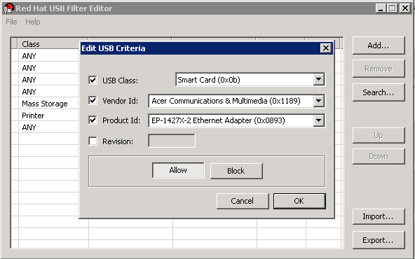
-
Click to save the changes.
You have added a USB policy to the USB Filter Editor. You need to export USB filter policies to the oVirt Engine for them to take effect.
Removing a USB Policy
Double-click the USB Filter Editor shortcut icon on your desktop. This opens the editor.
-
Select the policy to be removed.
-
Click Remove. A message displays prompting you to confirm that you want to remove the policy.
-
Click Yes to confirm that you want to remove the policy.
-
Click to save the changes.
You have removed a USB policy from the USB Filter Editor. You need to export USB filter policies to the oVirt Engine for them to take effect.
Searching for USB Device Policies
Search for attached USB devices to either allow or block them in the USB Filter Editor.
Double-click the USB Filter Editor shortcut icon on your desktop. This opens the editor.
-
Click Search. The Attached USB Devices window displays a list of all the attached devices.
-
Select the device and click Allow or Block as appropriate. Double-click the selected device to close the window. A policy rule for the device is added to the list.
-
Use the Up and Down buttons to change the position of the new policy rule in the list.
-
Click to save the changes.
You have searched the attached USB devices. USB filter policies need to be exported to the oVirt Engine to take effect.
Exporting a USB Policy
USB device policy changes need to be exported and uploaded to the oVirt Engine for the updated policy to take effect. Upload the policy and restart the ovirt-engine service.
Double-click the USB Filter Editor shortcut icon on your desktop. This opens the editor.
-
Click Export; the Save As window opens.
-
Save the file with a file name of usbfilter.txt.
-
Using a Secure Copy client, such as WinSCP, upload the usbfilter.txt file to the server running oVirt Engine. The file must be placed in the following directory on the server: /etc/ovirt-engine/
-
As the root user on the server running oVirt Engine, restart the ovirt-engine service.
# systemctl restart ovirt-engine.service
Importing a USB Policy
An existing USB device policy must be downloaded and imported into the USB Filter Editor before you can edit it.
-
Using a Secure Copy client, such as WinSCP, download the usbfilter.txt file from the server running oVirt Engine. The file can be found in the following directory on the server: /etc/ovirt-engine/
-
Double-click the USB Filter Editor shortcut icon on your desktop. This opens the editor.
-
Click Import. This opens the Open window.
-
Open the usbfilter.txt file that was downloaded from the server.
3.9.4. The Log Collector Tool
Log Collector
A log collection tool is included in the oVirt Engine. This allows you to easily collect relevant logs from across the oVirt environment when requesting support.
The log collection command is ovirt-log-collector. You are required to log in as the root user and provide the administration credentials for the oVirt environment. The ovirt-log-collector -h command displays usage information, including a list of all valid options for the ovirt-log-collector command.
Syntax for the ovirt-log-collector Command
The basic syntax for the log collector command is:
# ovirt-log-collector options  list all|clusters|datacenters
# ovirt-log-collector options collect
The two supported modes of operation are list and collect.
-
The
listparameter lists either the hosts, clusters, or data centers attached to the oVirt Engine. You are able to filter the log collection based on the listed objects. -
The
collectparameter performs log collection from the oVirt Engine. The collected logs are placed in an archive file under the /tmp/logcollector directory. Theovirt-log-collectorcommand assigns each log a specific file name.
Unless another parameter is specified, the default action is to list the available hosts together with the data center and cluster to which they belong. You will be prompted to enter user names and passwords to retrieve certain logs.
There are numerous parameters to further refine the ovirt-log-collector command.
General options
--version-
Displays the version number of the command in use and returns to prompt.
-h,--help-
Displays command usage information and returns to prompt.
--conf-file=PATH-
Sets PATH as the configuration file the tool is to use.
--local-tmp=PATH-
Sets PATH as the directory in which logs are saved. The default directory is /tmp/logcollector.
--ticket-number=TICKET-
Sets TICKET as the ticket, or case number, to associate with the SOS report.
--upload=FTP_SERVER-
Sets FTP_SERVER as the destination for retrieved logs to be sent using FTP.
--log-file=PATH-
Sets PATH as the specific file name the command should use for the log output.
--quiet-
Sets quiet mode, reducing console output to a minimum. Quiet mode is off by default.
-v,--verbose-
Sets verbose mode, providing more console output. Verbose mode is off by default.
--time-only-
Displays only information about time differences between hosts, without generating a full SOS report.
oVirt Engine Options
These options filter the log collection and specify authentication details for the oVirt Engine.
These parameters can be combined for specific commands. For example, ovirt-log-collector --user=admin@internal --cluster ClusterA,ClusterB --hosts "SalesHost"* specifies the user as admin@internal and limits the log collection to only SalesHost hosts in clusters A and B.
--no-hypervisors-
Omits virtualization hosts from the log collection.
--one-hypervisor-per-cluster-
Collects the logs of one host (the SPM, if there is one) from each cluster.
-u USER,--user=USER-
Sets the user name for login. The USER is specified in the format user@domain, where user is the user name and domain is the directory services domain in use. The user must exist in directory services and be known to the oVirt Engine.
-r FQDN,--rhevm=FQDN-
Sets the fully qualified domain name of the oVirt Engine from which to collect logs, where FQDN is replaced by the fully qualified domain name of the Engine. It is assumed that the log collector is being run on the same local host as the oVirt Engine; the default value is
localhost. -c CLUSTER,--cluster=CLUSTER-
Collects logs from the virtualization hosts in the nominated CLUSTER in addition to logs from the oVirt Engine. The cluster(s) for inclusion must be specified in a comma-separated list of cluster names or match patterns.
-d DATACENTER,--data-center=DATACENTER-
Collects logs from the virtualization hosts in the nominated DATACENTER in addition to logs from the oVirt Engine. The data center(s) for inclusion must be specified in a comma-separated list of data center names or match patterns.
-H HOSTS_LIST,--hosts=HOSTS_LIST-
Collects logs from the virtualization hosts in the nominated HOSTS_LIST in addition to logs from the oVirt Engine. The hosts for inclusion must be specified in a comma-separated list of host names, fully qualified domain names, or IP addresses. Match patterns are also valid.
SSH Configuration
--ssh-port=PORT-
Sets PORT as the port to use for SSH connections with virtualization hosts.
-k KEYFILE,--key-file=KEYFILE-
Sets KEYFILE as the public SSH key to be used for accessing the virtualization hosts.
--max-connections=MAX_CONNECTIONS-
Sets MAX_CONNECTIONS as the maximum concurrent SSH connections for logs from virtualization hosts. The default is
10.
PostgreSQL Database Options
The database user name and database name must be specified, using the pg-user and dbname parameters, if they have been changed from the default values.
Use the pg-dbhost parameter if the database is not on the local host. Use the optional pg-host-key parameter to collect remote logs. The PostgreSQL SOS plugin must be installed on the database server for remote log collection to be successful.
--no-postgresql-
Disables collection of database. The log collector will connect to the oVirt Engine PostgreSQL database and include the data in the log report unless the
--no-postgresqlparameter is specified. --pg-user=USER-
Sets USER as the user name to use for connections with the database server. The default is postgres.
--pg-dbname=DBNAME-
Sets DBNAME as the database name to use for connections with the database server. The default is rhevm.
--pg-dbhost=DBHOST-
Sets DBHOST as the host name for the database server. The default is localhost.
--pg-host-key=KEYFILE-
Sets KEYFILE as the public identity file (private key) for the database server. This value is not set by default; it is required only where the database does not exist on the local host.
Basic Log Collector Usage
When the ovirt-log-collector command is run without specifying any additional parameters, its default behavior is to collect all logs from the oVirt Engine and its attached hosts. It will also collect database logs unless the --no-postgresql parameter is added. In the following example, log collector is run to collect all logs from the oVirt Engine and three attached hosts.
# ovirt-log-collector
INFO: Gathering oVirt Engine information...
INFO: Gathering PostgreSQL the oVirt Engine database and log files from localhost...
Please provide REST API password for the admin@internal oVirt Engine user (CTRL+D to abort):
About to collect information from 3 hypervisors. Continue? (Y/n):
INFO: Gathering information from selected hypervisors...
INFO: collecting information from 192.168.122.250
INFO: collecting information from 192.168.122.251
INFO: collecting information from 192.168.122.252
INFO: finished collecting information from 192.168.122.250
INFO: finished collecting information from 192.168.122.251
INFO: finished collecting information from 192.168.122.252
Creating compressed archive...
INFO Log files have been collected and placed in /tmp/logcollector/sosreport-rhn-account-20110804121320-ce2a.tar.xz.
The MD5 for this file is 6d741b78925998caff29020df2b2ce2a and its size is 26.7M
3.9.5. The Engine Vacuum Tool
The Engine Vacuum Tool
The Engine Vacuum tool maintains PostgreSQL databases by updating tables and removing dead rows, allowing disk space to be reused. See the PostgreSQL documentation for information about the VACUUM command and its parameters.
The Engine Vacuum command is engine-vacuum. You must log in as the root user and provide the administration credentials for the oVirt environment.
Alternatively, the Engine Vacuum tool can be run while using the engine-setup command to customize an existing installation:
$ engine-setup
...
[ INFO  ] Stage: Environment customization
...
Perform full vacuum on the engine database engine@localhost?
This operation may take a while depending on this setup health and the
configuration of the db vacuum process.
See https://www.postgresql.org/docs/12/static/sql-vacuum.html
(Yes, No) [No]:
The Yes option runs the Engine Vacuum tool in full vacuum verbose mode.
Engine Vacuum Modes
Engine Vacuum has two modes:
- Standard Vacuum
-
Frequent standard vacuuming is recommended.
Standard vacuum removes dead row versions in tables and indexes and marks the space as available for future reuse. Frequently updated tables should be vacuumed on a regular basis. However, standard vacuum does not return the space to the operating system.
Standard vacuum, with no parameters, processes every table in the current database.
- Full Vacuum
-
Full vacuum is not recommended for routine use, but should only be run when a significant amount of space needs to be reclaimed from within the table.
Full vacuum compacts the tables by writing a new copy of the table file with no dead space, thereby enabling the operating system to reclaim the space. Full vacuum can take a long time.
Full vacuum requires extra disk space for the new copy of the table, until the operation completes and the old copy is deleted. Because full vacuum requires an exclusive lock on the table, it cannot be run in parallel with other uses of the table.
Syntax for the engine-vacuum Command
The basic syntax for the engine-vacuum command is:
# engine-vacuum# engine-vacuum optionRunning the engine-vacuum command with no options performs a standard vacuum.
There are several parameters to further refine the engine-vacuum command.
General Options
-h--help-
Displays information on how to use the
engine-vacuumcommand. -a-
Runs a standard vacuum, analyzes the database, and updates the optimizer statistics.
-A-
Analyzes the database and updates the optimizer statistics, without vacuuming.
-f-
Runs a full vacuum.
-v-
Runs in verbose mode, providing more console output.
-t table_name-
Vacuums a specific table or tables.
# engine-vacuum -f -v -t vm_dynamic -t vds_dynamic
3.9.6. The VDSM to Network Name Mapping Tool
Mapping VDSM Names to Logical Network Names
If the name of a logical network is longer than 15 characters or contains non-ASCII characters, the system automatically generates an on-host identifier (vdsm_name) name; it comprises the letters on and the first 13 characters of the network’s unique identifier, for example, ona1b2c3d4e5f6g. It is this name that appears in the host’s log files. To view a list of logical network names and their auto-generated network name, use the VDSM-to-Network-Name Mapping tool located in /usr/share/ovirt-engine/bin/.
-
The first time you run the tool, define a PASSWORD environment variable, which is the password of a database user with read access to the Engine database. For example, run:
# export PASSWORD=DatabaseUserPassword -
Run the VDSM-to-Network-Name Mapping tool:
# vdsm_to_network_name_map --user USER
where USER is the database user with read access to the Engine database, whose password is assigned to the PASSWORD environment variable.
The tool displays a list of logical network names that are mapped to their equivalent on-host identifiers.
You can run the tool with the following flags:
--host is the hostname/IP address of the database server. The default value is localhost.
--port is the port number of the database server. The default value is 5432.
--database is the name of the database. The default value is engine, which is the Engine database.
--secure enables a secure connection with the database. By default the tool is run without a secure connection.
4. Gathering Information About the Environment
4.1. Monitoring and observability
This chapter provides a number of ways to monitor and obtain metrics and logs from your oVirt system. These methods include:
-
Using Data Warehouse and Grafana to monitor oVirt
-
Sending metrics to a remote instance of Elasticsearch
-
Deploying Insights in Red Hat Virtualization Manager
4.1.1. Using Data Warehouse and Grafana to monitor oVirt
Grafana overview
Grafana is a web-based UI tool used to display reports based on data collected from the oVirt Data Warehouse PostgreSQL database under the database name ovirt_engine_history. For details of the available report dashboards, see Grafana dashboards and Grafana website - dashboards.
Data from the Engine is collected every minute and aggregated in hourly and daily aggregations. The data is retained according to the scale setting defined in the Data Warehouse configuration during engine-setup (Basic or Full scale):
-
Basic (default) - samples data saved for 24 hours, hourly data saved for 1 month, daily data - no daily aggregations saved.
-
Full (recommended)- samples data saved for 24 hours, hourly data saved for 2 months, daily aggregations saved for 5 years.
Full sample scaling may require migrating the Data Warehouse to a separate virtual machine.
-
For Data Warehouse scaling instructions, see Changing the Data Warehouse Sampling Scale.
-
For instructions on migrating the Data Warehouse to or installing on a separate machine, see Migrating Data Warehouse to a Separate Machine and Installing and Configuring Data Warehouse on a Separate Machine.
|
oVirt only supports installing the Data Warehouse database, the Data Warehouse service and Grafana all on the same machine as each other, even though you can install each of these components on separate machines from each other. |
Installation
Grafana integration is enabled and installed by default when you run oVirt Engine engine-setup in a Stand Alone Manager installation, and in the Self-Hosted engine installation.
|
Grafana is not installed by default and you may need to install it manually under some scenarios such as performing an upgrade from an earlier version of oVirt, restoring a backup, or when the Data Warehouse is migrated to a separate machine. |
To enable Grafana integration manually:
-
Put the environment in global maintenance mode:
# hosted-engine --set-maintenance --mode=global -
Log in to the machine where you want to install Grafana. This should be the same machine where the Data Warehouse is configured; usually the Engine machine.
-
Run the
engine-setupcommand as follows:# engine-setup --reconfigure-optional-components
-
Answer
Yesto install Grafana on this machine:Configure Grafana on this host (Yes, No) [Yes]:
-
Disable global maintenance mode:
# hosted-engine --set-maintenance --mode=none
To access the Grafana dashboards:
-
Go to
https://<engine FQDN or IP address>/ovirt-engine-grafana
or
-
Click Monitoring Portal in the web administration welcome page for the Administration Portal.
Configuring Grafana for Single Sign-on
The Engine engine-setup automatically configures Grafana to allow existing users on the Engine to log in with SSO from the Administration Portal, but does not automatically create users. You need to create new users (Invite in the Grafana UI), confirm the new user, and then they can log in.
-
Set an email address for the user in the Engine, if it is not already defined.
-
Log in to Grafana with an existing admin user (the initially configured admin).
-
Go to and select Invite.
-
Input the email address and name, and select a Role.
-
Send the invitation using one of these options:
-
Select Send invite mail and click Submit. For this option, you need an operational local mail server configured on the Grafana machine.
or
-
Select Pending Invites
-
Locate the entry you want
-
Select Copy invite
-
Copy and use this link to create the account by pasting it directly into a browser address bar, or by sending it to another user.
-
-
If you use the Pending Invites option, no email is sent, and the email address does not really need to exist - any valid looking address will work, as long as it’s configured as the email address of a Engine user.
-
Log in to the oVirt web administration welcome page using the account that has this email address.
-
Select
Monitoring Portalto open the Grafana dashboard. -
Select Sign in with oVirt Engine Auth.
Built-in Grafana dashboards
The following dashboards are available in the initial Grafana setup to report Data Center, Cluster, Host, and Virtual Machine data:
| Dashboard type | Content |
|---|---|
Executive dashboards |
|
Inventory dashboards |
|
Service Level dashboards |
|
Trend dashboards |
|
|
The Grafana dashboards includes direct links to the oVirt Administration Portal, allowing you to quickly view additional details for your clusters, hosts, and virtual machines. |
Customized Grafana dashboards
You can create customized dashboards or copy and modify existing dashboards according to your reporting needs.
|
Built-in dashboards cannot be customized. |
4.1.2. Sending metrics and logs to a remote instance of Elasticsearch
|
Red Hat does not own or maintain Elasticsearch. You need to have a working familiarity with Elasticsearch setup and maintenance to deploy this option. |
You can configure the oVirt Engine and hosts to send metrics data and logs to your existing Elasticsearch instance.
To do this, run the Ansible role that configures collectd and rsyslog on the Engine and all hosts to collect engine.log, vdsm.log, and collectd metrics, and send them to your Elasticsearch instance.
For more information, including a full list with explanations of available Metrics Schema, see Sending RHV monitoring data to a remote Elasticsearch instance.
Installing collectd and rsyslog
Deploy collectd and rsyslog on the hosts to collect logs and metrics.
|
You do not need to repeat this procedure for new hosts. Every new host that is added is automatically configured by the Engine to send the data to Elasticsearch during host-deploy. |
-
Log in to the Engine machine using SSH.
-
Copy
/etc/ovirt-engine-metrics/config.yml.exampleto create/etc/ovirt-engine-metrics/config.yml.d/config.yml:# cp /etc/ovirt-engine-metrics/config.yml.example /etc/ovirt-engine-metrics/config.yml.d/config.yml -
Edit the
ovirt_env_nameandelasticsearch_hostparameters inconfig.ymland save the file. The following additional parameters can be added to the file:use_omelasticsearch_cert: false rsyslog_elasticsearch_usehttps_metrics: !!str off rsyslog_elasticsearch_usehttps_logs: !!str off
-
When using certificates, set
use_omelasticsearch_certto true. -
To disable logs or metrics, use the
rsyslog_elasticsearch_usehttps_metricsand/orrsyslog_elasticsearch_usehttps_logsparameters.
-
-
Deploy
collectdandrsyslogon the hosts:# /usr/share/ovirt-engine-metrics/setup/ansible/configure_ovirt_machines_for_metrics.shThe
configure_ovirt_machines_for_metrics.shscript runs an Ansible role that includeslinux-system-roles(see Administration and configuration tasks using System Roles in RHEL) and uses it to deploy and configurersyslogon the host.rsyslogcollects metrics fromcollectdand sends them to Elasticsearch.
Logging schema and analyzing logs
Use the Discover page to interactively explore data collected from oVirt. Each set of results that is collected is referred to as a document. Documents are collected from the following log files:
-
engine.log- contains all oVirt Engine UI crashes, Active Directory lookups, database issues, and other events. -
vdsm.log- the log file for the VDSM, the Engine’s agent on the virtualization hosts, and contains host-related events.
The following fields are available:
| parameter | description |
|---|---|
_id |
The unique ID of the document |
_index |
The ID of the index to which the document belongs. The index with the |
hostname |
For the engine.log this is the hostname of the Engine. For the vdsm.log this is the hostname of the host. |
level |
The log record severity: TRACE, DEBUG, INFO, WARN, ERROR, FATAL. |
message |
The body of the document message. |
ovirt.class |
The name of a Java class that produced this log. |
ovirt.correlationid |
For the engine.log only. This ID is used to correlate the multiple parts of a single task performed by the Engine. |
ovirt.thread |
The name of a Java thread inside which the log record was produced. |
tag |
Predefined sets of metadata that can be used to filter the data. |
@timestamp |
The [time](Troubleshooting#information-is-missing-from-kibana) that the record was issued. |
_score |
N/A |
_type |
N/A |
ipaddr4 |
The machine’s IP address. |
ovirt.cluster_name |
For the vdsm.log only. The name of the cluster to which the host belongs. |
ovirt.engine_fqdn |
The Engine’s FQDN. |
ovirt.module_lineno |
The file and line number within the file that ran the command defined in |
4.2. Log Files
4.2.1. Engine Installation Log Files
| Log File | Description |
|---|---|
/var/log/ovirt-engine/engine-cleanup_yyyy_mm_dd_hh_mm_ss.log |
Log from the |
/var/log/ovirt-engine/engine-db-install-yyyy_mm_dd_hh_mm_ss.log |
Log from the |
/var/log/ovirt-engine/ovirt-engine-dwh-setup-yyyy_mm_dd_hh_mm_ss.log |
Log from the |
/var/log/ovirt-engine/setup/ovirt-engine-setup-yyyymmddhhmmss.log |
Log from the |
4.2.2. oVirt Engine Log Files
| Log File | Description |
|---|---|
/var/log/ovirt-engine/engine.log |
Reflects all oVirt Engine GUI crashes, Active Directory lookups, Database issues, and other events. |
/var/log/ovirt-engine/host-deploy |
Log files from hosts deployed from the oVirt Engine. |
/var/lib/ovirt-engine/setup-history.txt |
Tracks the installation and upgrade of packages associated with the oVirt Engine. |
/var/log/httpd/ovirt-requests-log |
Logs files from requests made to the oVirt Engine via HTTPS, including how long each request took. A |
/var/log/ovn-provider/ovirt-provider-ovn.log |
Logs the activities of the OVN provider. For information about Open vSwitch logs, see the Open vSwitch documentation. |
4.2.3. SPICE Log Files
SPICE log files are useful when troubleshooting SPICE connection issues. To start SPICE debugging, change the log level to debugging. Then, identify the log location.
Both the clients used to access the guest machines and the guest machines themselves have SPICE log files. For client-side logs, if a SPICE client was launched using the native client, for which a console.vv file is downloaded, use the remote-viewer command to enable debugging and generate log output.
SPICE Logs for Hypervisor SPICE Servers
| Log Type | Log Location | To Change Log Level: |
|---|---|---|
Host/Hypervisor SPICE Server |
/var/log/libvirt/qemu/(guest_name).log |
Run |
SPICE Logs for Guest Machines
| Log Type | Log Location | To Change Log Level: |
|---|---|---|
Windows Guest |
C:\Windows\Temp\vdagent.log C:\Windows\Temp\vdservice.log |
Not applicable |
Enterprise Linux Guest |
Use |
To run the To run $ killall - u $USER spice-vdagent $ spice-vdagent -x -d [-d] [ |& tee spice-vdagent.log ] |
SPICE Logs for SPICE Clients Launched Using console.vv Files
For Linux client machines:
-
Enable SPICE debugging by running the
remote-viewercommand with the--spice-debugoption. When prompted, enter the connection URL, for example, spice://virtual_machine_IP:port.# remote-viewer --spice-debug -
To run SPICE client with the debug parameter and to pass a .vv file to it, download the console.vv file and run the
remote-viewercommand with the--spice-debugoption and specify the full path to the console.vv file.# remote-viewer --spice-debug /path/to/console.vv
For Windows client machines:
-
In versions of
virt-viewer2.0-11.el7ev and later, virt-viewer.msi installsvirt-vieweranddebug-viewer.exe. -
Run the
remote-viewercommand with thespice-debugargument and direct the command at the path to the console:remote-viewer --spice-debug path\to\console.vv -
To view logs, connect to the virtual machine, and you will see a command prompt running GDB that prints standard output and standard error of
remote-viewer.
4.2.4. Host Log Files
| Log File | Description |
|---|---|
/var/log/messages |
The log file used by |
/var/log/vdsm/spm-lock.log |
Log file detailing the host’s ability to obtain a lease on the Storage Pool Manager role. The log details when the host has acquired, released, renewed, or failed to renew the lease. |
/var/log/vdsm/vdsm.log |
Log file for VDSM, the Engine’s agent on the host(s). |
/tmp/ovirt-host-deploy-Date.log |
A host deployment log that is copied to the Engine as |
/var/log/vdsm/import/import-UUID-Date.log |
Log file detailing virtual machine imports from a KVM host, a VMWare provider, or a RHEL 5 Xen host, including import failure information. UUID is the UUID of the virtual machine that was imported and Date is the date and time that the import began. |
/var/log/vdsm/supervdsm.log |
Logs VDSM tasks that were executed with superuser permissions. |
/var/log/vdsm/upgrade.log |
VDSM uses this log file during host upgrades to log configuration changes. |
/var/log/vdsm/mom.log |
Logs the activities of the VDSM’s memory overcommitment manager. |
4.2.5. Setting debug-level logging for oVirt services
|
Setting logging to debug-level may expose sensitive information such as passwords or internal VM data. Make sure that non-trusted or unauthorized users do not have access to debug logs. |
You can set the logs of the following oVirt (oVirt) services to debug-level by modifying the sysconfig file of each service.
| Service | File path |
|---|---|
|
|
|
|
|
|
|
|
This modification affects logging done by the Python wrapper, not the main service process.
Setting logging to debug-level is useful for debugging issues related to start up - for example, if the main process fails to start due to a missing or incorrect Java runtime or library.
-
Verify that the
sysconfigfile you want to modify exists. If necessary, create it.
-
Add the following to the
sysconfigfile of the service:OVIRT_SERVICE_DEBUG=1 -
Restart the service:
# systemctl restart <service>
The sysconfig log file of the service is now set to debug-level.
Logging caused by this setting goes to the system log, so the logs it generates can be found in /var/log/messages, not in the service-specific log file, or by using the journalctl command.
4.2.6. Main configuration files for oVirt services
In addition to a sysconfig file, each of these oVirt (oVirt) services has another configuration file that is used more often.
| Service | sysconfig file path | Main configuration file |
|---|---|---|
|
|
|
|
|
|
|
|
|
|
|
|
4.2.7. Setting Up a Host Logging Server
Hosts generate and update log files, recording their actions and problems. Collecting these log files centrally simplifies debugging.
This procedure should be used on your centralized log server. You could use a separate logging server, or use this procedure to enable host logging on the oVirt Engine.
-
Check to see if the firewall allows traffic on the
UDP 514port, and is open tosyslogservice traffic:# firewall-cmd --query-service=syslogIf the output is
no, allow traffic on theUDP 514port with:# firewall-cmd --add-service=syslog --permanent # firewall-cmd --reload
-
Create a new
.conffile on the syslog server, for example,/etc/rsyslog.d/from_remote.conf, and add the following lines:template(name="DynFile" type="string" string="/var/log/%HOSTNAME%/%PROGRAMNAME%.log") RuleSet(name="RemoteMachine"){ action(type="omfile" dynaFile="DynFile") } Module(load="imudp") Input(type="imudp" port="514" ruleset="RemoteMachine") -
Restart the
rsyslogservice:# systemctl restart rsyslog.service -
Log in to the hypervisor, and in the
/etc/rsyslog.confadd the following line:*.info;mail.none;authpriv.none;cron.none @<syslog-FQDN>:514 -
Restart the rsyslog service on the hypervisor.
# systemctl restart rsyslog.service
Your centralized log server is now configured to receive and store the messages and secure logs from your virtualization hosts.
4.2.8. Enabling SyslogHandler to pass oVirt Engine logs to a remote syslog server
This implementation uses the JBoss EAP SyslogHandler log manager and enables passing log records from the engine.log and server.log to a syslog server.
|
oVirt versions earlier than oVirt 4.4.10 featured similar functionality provided by
|
Use this procedure on the central syslog server. You can use a separate logging server, or use this procedure to pass the engine.log and server.log files from the Engine to the syslog server. See also the configuration procedure Setting up a Host Logging Server.
-
Create the configuration file
90-syslog.confin the/etc/ovirt-engine/engine.conf.ddirectory and add the following content:SYSLOG_HANDLER_ENABLED=true SYSLOG_HANDLER_SERVER_HOSTNAME=localhost SYSLOG_HANDLER_FACILITY=USER_LEVEL
-
Install and configure
rsyslog.# dnf install rsyslog
-
Configure SELinux to allow
rsyslogtraffic.# semanage port -a -t syslogd_port_t -p udp 514
-
Create the configuration file
/etc/rsyslog.d/rhvm.confand add the following content:user.* /var/log/jboss.log module(load="imudp") # needs to be done just once input(type="imudp" port="514")
-
Restart the rsyslog service.
# systemctl restart rsyslog.service
-
If the firewall is enabled and active, run the following command to add the necessary rules for opening the
rsyslogports inFirewalld:# firewall-cmd --permanent --add-port=514/udp # firewall-cmd --reload
-
Restart oVirt Engine.
# systemctl restart ovirt-engine
The syslog server can now receive and store the engine.log files.
Appendix A: VDSM Service and Hooks
The VDSM service is used by the oVirt Engine to manage oVirt Nodes (oVirt Node) and Enterprise Linux hosts. VDSM manages and monitors the host’s storage, memory, and network resources. It also coordinates virtual machine creation, statistics gathering, log collection and other host administration tasks. VDSM is run as a daemon on each host managed by oVirt Engine. It answers XML-RPC calls from clients. The oVirt Engine functions as a VDSM client.
VDSM is extensible via hooks. Hooks are scripts executed on the host when key events occur. When a supported event occurs VDSM runs any executable hook scripts in /usr/libexec/vdsm/hooks/nn_event-name/ on the host in alphanumeric order. By convention each hook script is assigned a two digit number, included at the front of the file name, to ensure that the order in which the scripts will be run in is clear. You are able to create hook scripts in any programming language, Python will however be used for the examples contained in this chapter.
Note that all scripts defined on the host for the event are executed. If you require that a given hook is only executed for a subset of the virtual machines which run on the host then you must ensure that the hook script itself handles this requirement by evaluating the Custom Properties associated with the virtual machine.
|
VDSM hooks can interfere with the operation of oVirt. A bug in a VDSM hook has the potential to cause virtual machine crashes and loss of data. VDSM hooks should be implemented with caution and tested rigorously. The Hooks API is new and subject to significant change in the future. |
You can extend VDSM with event-driven hooks. Extending VDSM with hooks is an experimental technology, and this chapter is intended for experienced developers.
By setting custom properties on virtual machines it is possible to pass additional parameters, specific to a given virtual machine, to the hook scripts.
Installing a VDSM hook
By default, VDSM hooks are not installed. If you need a specific hook, you must install it manually.
-
The host repository must be enabled.
-
You are logged into the host with root permissions.
-
Get a list of available hooks:
# dnf list vdsm\*hook\*
-
Put the host in maintenance mode.
-
Install the desired VDSM hook package on the host:
# dnf install <vdsm-hook-name>
For example, to install the
vdsm-hook-vhostmdpackage on the host, enter the following:# dnf install vdsm-hook-vhostmd
-
Restart the host.
Supported VDSM Events
| Name | Description |
|---|---|
before_vm_start |
Before virtual machine starts. |
after_vm_start |
After virtual machine starts. |
before_vm_cont |
Before virtual machine continues. |
after_vm_cont |
After virtual machine continues. |
before_vm_pause |
Before virtual machine pauses. |
after_vm_pause |
After virtual machine pauses. |
before_vm_hibernate |
Before virtual machine hibernates. |
after_vm_hibernate |
After virtual machine hibernates. |
before_vm_dehibernate |
Before virtual machine dehibernates. |
after_vm_dehibernate |
After virtual machine dehibernates. |
before_vm_migrate_source |
Before virtual machine migration, run on the source host from which the migration is occurring. |
after_vm_migrate_source |
After virtual machine migration, run on the source host from which the migration is occurring. |
before_vm_migrate_destination |
Before virtual machine migration, run on the destination host to which the migration is occurring. |
after_vm_migrate_destination |
After virtual machine migration, run on the destination host to which the migration is occurring. |
after_vm_destroy |
After virtual machine destruction. |
before_vdsm_start |
Before VDSM is started on the host. before_vdsm_start hooks are executed as the user root, and do not inherit the environment of the VDSM process. |
after_vdsm_stop |
After VDSM is stopped on the host. after_vdsm_stop hooks are executed as the user root, and do not inherit the environment of the VDSM process. |
before_nic_hotplug |
Before the NIC is hot plugged into the virtual machine. |
after_nic_hotplug |
After the NIC is hot plugged into the virtual machine. |
before_nic_hotunplug |
Before the NIC is hot unplugged from the virtual machine |
after_nic_hotunplug |
After the NIC is hot unplugged from the virtual machine. |
after_nic_hotplug_fail |
After hot plugging the NIC to the virtual machine fails. |
after_nic_hotunplug_fail |
After hot unplugging the NIC from the virtual machine fails. |
before_disk_hotplug |
Before the disk is hot plugged into the virtual machine. |
after_disk_hotplug |
After the disk is hot plugged into the virtual machine. |
before_disk_hotunplug |
Before the disk is hot unplugged from the virtual machine |
after_disk_hotunplug |
After the disk is hot unplugged from the virtual machine. |
after_disk_hotplug_fail |
After hot plugging the disk to the virtual machine fails. |
after_disk_hotunplug_fail |
After hot unplugging the disk from the virtual machine fails. |
before_device_create |
Before creating a device that supports custom properties. |
after_device_create |
After creating a device that supports custom properties. |
before_update_device |
Before updating a device that supports custom properties. |
after_update_device |
After updating a device that supports custom properties. |
before_device_destroy |
Before destroying a device that supports custom properties. |
after_device_destroy |
After destroying a device that supports custom properties. |
before_device_migrate_destination |
Before device migration, run on the destination host to which the migration is occurring. |
after_device_migrate_destination |
After device migration, run on the destination host to which the migration is occurring. |
before_device_migrate_source |
Before device migration, run on the source host from which the migration is occurring. |
after_device_migrate_source |
After device migration, run on the source host from which the migration is occurring. |
after_network_setup |
After setting up the network when starting a host machine. |
before_network_setup |
Before setting up the network when starting a host machine. |
The VDSM Hook Environment
Most hook scripts are run as the vdsm user and inherit the environment of the VDSM process. The exceptions are hook scripts triggered by the before_vdsm_start and after_vdsm_stop events. Hook scripts triggered by these events run as the root user and do not inherit the environment of the VDSM process.
The VDSM Hook Domain XML Object
VDSM uses the libvirt domain XML format to define virtual machines. The UUID of the virtual machine may be deduced from the domain XML, but it is also available as the environment variable vmId.
When hook scripts are started, the _hook_domxml variable is appended to the environment. This variable contains the path of the libvirt domain XML representation of the relevant virtual machine.
Some hooks are an exception to this rule. The following hooks contain the XML representation of the NIC, not the virtual machine:
-
*_nic_hotplug_* -
*_nic_hotunplug_* -
*_update_device -
*_device_create -
*_device_migrate_*
|
The |
Defining Custom Properties
The custom properties that are accepted by the oVirt Engine - and in turn passed to custom hooks - are defined using the engine-config command. Run this command as the root user on the host where oVirt Engine is installed.
The UserDefinedVMProperties and CustomDeviceProperties configuration keys are used to store the names of the custom properties supported. Regular expressions defining the valid values for each named custom property are also contained in these configuration keys.
Multiple custom properties are separated by a semi-colon. Note that when setting the configuration key, any existing value it contained is overwritten. When combining new and existing custom properties, all of the custom properties in the command used to set the key’s value must be included.
Once the configuration key has been updated, the ovirt-engine service must be restarted for the new values to take effect.
smartcard Custom Property-
Check the existing custom properties defined by the
UserDefinedVMPropertiesconfiguration key using the following command:# engine-config -g UserDefinedVMPropertiesAs shown by the output below, the custom property
memoryis already defined. The regular expression^[0-9]+$ensures that the custom property will only ever contain numeric characters.# engine-config -g UserDefinedVMProperties UserDefinedVMProperties: version: 4.3 UserDefinedVMProperties: version: 4.4 UserDefinedVMProperties : memory=^[0-9]+$ version: 4.4
-
Because the
memorycustom property is already defined in theUserDefinedVMPropertiesconfiguration key, the new custom property must be appended to it. The additional custom property,smartcard, is added to the configuration key’s value. The new custom property is able to hold a value oftrueorfalse.# engine-config -s UserDefinedVMProperties='memory=^[0-9]+$;smartcard=^(true|false)$' --cver=4.4
-
Verify that the custom properties defined by the
UserDefinedVMPropertiesconfiguration key have been updated correctly.# engine-config -g UserDefinedVMProperties UserDefinedVMProperties: version: 4.3 UserDefinedVMProperties: version: 4.4 UserDefinedVMProperties : memory=^[0-9]+$;smartcard=^(true|false)$ version: 4.4
-
Finally, the ovirt-engine service must be restarted for the configuration change to take effect.
# systemctl restart ovirt-engine.service
interface Custom Property-
Check the existing custom properties defined by the
CustomDevicePropertiesconfiguration key using the following command:# engine-config -g CustomDeviceProperties
As shown by the output below, no custom properties have yet been defined.
# engine-config -g CustomDeviceProperties
CustomDeviceProperties:  version: 4.3
CustomDeviceProperties:  version: 4.4
-
The
interfacecustom property does not already exist, so it can be appended as is. In this example, the value of thespeedsub-property is set to a range of 0 to 99999, and the value of theduplexsub-property is set to a selection of eitherfullorhalf.# engine-config -s CustomDeviceProperties="{type=interface;prop={speed=^([0-9]{1,5})$;duplex=^(full|half)$}}" --cver=4.4 -
Verify that the custom properties defined by the
CustomDevicePropertiesconfiguration key have been updated correctly.# engine-config -g CustomDeviceProperties UserDefinedVMProperties: version: 4.3 UserDefinedVMProperties: version: 4.4 UserDefinedVMProperties : {type=interface;prop={speed=^([0-9]{1,5})$;duplex=^(full|half)$}} version: 4.4 -
Finally, the ovirt-engine service must be restarted for the configuration change to take effect.
# systemctl restart ovirt-engine.service
Setting Virtual Machine Custom Properties
Once custom properties are defined in the oVirt Engine, you can begin setting them on virtual machines. Custom properties are set on the Custom Properties tab of the New Virtual Machine and Edit Virtual Machine windows in the Administration Portal.
You can also set custom properties from the Run Virtual Machine(s) dialog box. Custom properties set from the Run Virtual Machine(s) dialog box will only apply to the virtual machine until it is next shutdown.
The Custom Properties tab provides a facility for you to select from the list of defined custom properties. Once you select a custom property key an additional field will display allowing you to enter a value for that key. Add additional key/value pairs by clicking the + button and remove them by clicking the - button.
Evaluating Virtual Machine Custom Properties in a VDSM Hook
Each key set in the Custom Properties field for a virtual machine is appended as an environment variable when calling hook scripts. Although the regular expressions used to validate the Custom Properties field provide some protection you should ensure that your scripts also validate that the inputs provided match their expectations.
This short Python example checks for the existence of the custom property key1. If the custom property is set then the value is printed to standard error. If the custom property is not set then no action is taken.
#!/usr/bin/python

import os
import sys

if os.environ.has_key('key1'):
        sys.stderr.write('key1 value was : %s\n' % os.environ['key1'])
else:
    sys.exit(0)
Using the VDSM Hooking Module
VDSM ships with a Python hooking module, providing helper functions for VDSM hook scripts. This module is provided as an example, and is only relevant to VDSM hooks written in Python.
The hooking module supports reading of a virtual machine’s libvirt XML into a DOM object. Hook scripts can then use Python’s built-in xml.dom library to manipulate the object.
The modified object can then be saved back to libvirt XML using the hooking module. The hooking module provides the following functions to support hook development:
| Name | Argument | Description |
|---|---|---|
|
string |
Converts a string "true" or "false" to a Boolean value |
|
- |
Reads the virtual machine’s libvirt XML into a DOM object |
|
DOM object |
Writes the virtual machine’s libvirt XML from a DOM object |
VDSM Hook Execution
before_vm_start scripts can edit the domain XML in order to change VDSM’s definition of a virtual machine before it reaches libvirt. Caution must be exercised in doing so. Hook scripts have the potential to disrupt the operation of VDSM, and buggy scripts can result in outages to the oVirt environment. In particular, ensure you never change the UUID of the domain, and do not attempt to remove a device from the domain without sufficient background knowledge.
Both before_vdsm_start and after_vdsm_stop hook scripts are run as the root user. Other hook scripts that require root access to the system must be written to use the sudo command for privilege escalation. To support this the /etc/sudoers must be updated to allow the vdsm user to use sudo without reentering a password. This is required as hook scripts are executed non-interactively.
sudo for VDSM HooksIn this example the sudo command will be configured to allow the vdsm user to run the /bin/chown command as root.
-
Log into the virtualization host as root.
-
Open the /etc/sudoers file in a text editor.
-
Add this line to the file:
vdsm ALL=(ALL) NOPASSWD: /bin/chownThis specifies that the vdsm user has the ability to run the
/bin/chowncommand as the root user. TheNOPASSWDparameter indicates that the user will not be prompted to enter their password when callingsudo.
Once this configuration change has been made VDSM hooks are able to use the sudo command to run /bin/chown as root. This Python code uses sudo to execute /bin/chown as root on the file /my_file.
retcode = subprocess.call( ["/usr/bin/sudo", "/bin/chown", "root", "/my_file"] )The standard error stream of hook scripts is collected in VDSM’s log. This information is used to debug hook scripts.
VDSM Hook Return Codes
Hook scripts must return one of the return codes shown in hook return codes. The return code will determine whether further hook scripts are processed by VDSM.
| Code | Description |
|---|---|
0 |
The hook script ended successfully |
1 |
The hook script failed, other hooks should be processed |
2 |
The hook script failed, no further hooks should be processed |
>2 |
Reserved |
VDSM Hook Examples
You must ensure that any and all hook scripts that you install to your system, regardless of source, are thoroughly tested for your environment.
Purpose:
This hook script allows for tuning the allocation of memory on a NUMA host based on the numaset custom property. Where the custom property is not set no action is taken.
Configuration String:
numaset=^(interleave|strict|preferred):[\^]?\d+(-\d+)?(,[\^]?\d+(-\d+)?)*$
The regular expression used allows the numaset custom property for a given virtual machine to specify both the allocation mode (interleave, strict, preferred) and the node to use. The two values are separated by a colon (:). The regular expression allows specification of the nodeset as:
-
that a specific node (
numaset=strict:1, specifies that only node 1 be used), or -
that a range of nodes be used (
numaset=strict:1-4, specifies that nodes 1 through 4 be used), or -
that a specific node not be used (
numaset=strict:^3, specifies that node 3 not be used), or -
any comma-separated combination of the above (
numaset=strict:1-4,6, specifies that nodes 1 to 4, and 6 be used).
Script:
/usr/libexec/vdsm/hooks/before_vm_start/50_numa
#!/usr/bin/python

import os
import sys
import hooking
import traceback

'''
numa hook
=========
add numa support for domain xml:

<numatune>
    <memory mode="strict" nodeset="1-4,^3" />
</numatune>

memory=interleave|strict|preferred

numaset="1" (use one NUMA node)
numaset="1-4" (use 1-4 NUMA nodes)
numaset="^3" (don't use NUMA node 3)
numaset="1-4,^3,6" (or combinations)

syntax:
    numa=strict:1-4
'''

if os.environ.has_key('numa'):
    try:
        mode, nodeset = os.environ['numa'].split(':')

        domxml = hooking.read_domxml()

        domain = domxml.getElementsByTagName('domain')[0]
        numas = domxml.getElementsByTagName('numatune')

        if not len(numas) > 0:
            numatune = domxml.createElement('numatune')
            domain.appendChild(numatune)

            memory = domxml.createElement('memory')
            memory.setAttribute('mode', mode)
            memory.setAttribute('nodeset', nodeset)
            numatune.appendChild(memory)

            hooking.write_domxml(domxml)
        else:
            sys.stderr.write('numa: numa already exists in domain xml')
            sys.exit(2)
    except:
        sys.stderr.write('numa: [unexpected error]: %s\n' % traceback.format_exc())
        sys.exit(2)
Appendix B: Custom Network Properties
Explanation of bridge_opts Parameters
| Parameter | Description |
|---|---|
forward_delay |
Sets the time, in deciseconds, a bridge will spend in the listening and learning states. If no switching loop is discovered in this time, the bridge will enter forwarding state. This allows time to inspect the traffic and layout of the network before normal network operation. |
group_addr |
To send a general query, set this value to zero. To send a group-specific and group-and-source-specific queries, set this value to a 6-byte MAC address, not an IP address. Allowed values are |
group_fwd_mask |
Enables bridge to forward link local group addresses. Changing this value from the default will allow non-standard bridging behavior. |
hash_max |
The maximum amount of buckets in the hash table. This takes effect immediately and cannot be set to a value less than the current number of multicast group entries. Value must be a power of two. |
hello_time |
Sets the time interval, in deciseconds, between sending 'hello' messages, announcing bridge position in the network topology. Applies only if this bridge is the Spanning Tree root bridge. |
max_age |
Sets the maximum time, in deciseconds, to receive a 'hello' message from another root bridge before that bridge is considered dead and takeover begins. |
multicast_last_member_count |
Sets the number of 'last member' queries sent to the multicast group after receiving a 'leave group' message from a host. |
multicast_last_member_interval |
Sets the time, in deciseconds, between 'last member' queries. |
multicast_membership_interval |
Sets the time, in deciseconds, that a bridge will wait to hear from a member of a multicast group before it stops sending multicast traffic to the host. |
multicast_querier |
Sets whether the bridge actively runs a multicast querier or not. When a bridge receives a 'multicast host membership' query from another network host, that host is tracked based on the time that the query was received plus the multicast query interval time. If the bridge later attempts to forward traffic for that multicast membership, or is communicating with a querying multicast router, this timer confirms the validity of the querier. If valid, the multicast traffic is delivered via the bridge’s existing multicast membership table; if no longer valid, the traffic is sent via all bridge ports.Broadcast domains with, or expecting, multicast memberships should run at least one multicast querier for improved performance. |
multicast_querier_interval |
Sets the maximum time, in deciseconds, between last 'multicast host membership' query received from a host to ensure it is still valid. |
multicast_query_use_ifaddr |
Boolean. Defaults to '0', in which case the querier uses 0.0.0.0 as source address for IPv4 messages. Changing this sets the bridge IP as the source address. |
multicast_query_interval |
Sets the time, in deciseconds, between query messages sent by the bridge to ensure validity of multicast memberships. At this time, or if the bridge is asked to send a multicast query for that membership, the bridge checks its own multicast querier state based on the time that a check was requested plus multicast_query_interval. If a multicast query for this membership has been sent within the last multicast_query_interval, it is not sent again. |
multicast_query_response_interval |
Length of time, in deciseconds, a host is allowed to respond to a query once it has been sent.Must be less than or equal to the value of the multicast_query_interval. |
multicast_router |
Allows you to enable or disable ports as having multicast routers attached. A port with one or more multicast routers will receive all multicast traffic. A value of 0 disables completely, a value of 1 enables the system to automatically detect the presence of routers based on queries, and a value of 2 enables ports to always receive all multicast traffic. |
multicast_snooping |
Toggles whether snooping is enabled or disabled. Snooping allows the bridge to listen to the network traffic between routers and hosts to maintain a map to filter multicast traffic to the appropriate links.This option allows the user to re-enable snooping if it was automatically disabled due to hash collisions, however snooping will not be re-enabled if the hash collision has not been resolved. |
multicast_startup_query_count |
Sets the number of queries sent out at startup to determine membership information. |
multicast_startup_query_interval |
Sets the time, in deciseconds, between queries sent out at startup to determine membership information. |
How to Set Up oVirt Engine to Use Ethtool
You can configure ethtool properties for host network interface cards from the Administration Portal. The ethtool_opts key is not available by default and needs to be added to the Engine using the engine configuration tool. You also need to install the required VDSM hook package on the hosts.
Adding the ethtool_opts Key to the Engine
-
On the Engine, run the following command to add the key:
# engine-config -s UserDefinedNetworkCustomProperties=ethtool_opts=.* --cver=4.4 -
Restart the
ovirt-engineservice:# systemctl restart ovirt-engine.service -
On the hosts that you want to configure ethtool properties, install the VDSM hook package. The package is available by default on oVirt Node but needs to be installed on Enterprise Linux hosts.
# dnf install vdsm-hook-ethtool-options
The ethtool_opts key is now available in the Administration Portal. See Editing Host Network Interfaces and Assigning Logical Networks to Hosts to apply ethtool properties to logical networks.
How to Set Up oVirt Engine to Use FCoE
You can configure Fibre Channel over Ethernet (FCoE) properties for host network interface cards from the Administration Portal. The fcoe key is not available by default and needs to be added to the Engine using the engine configuration tool. You can check whether fcoe has already been enabled by running the following command:
# engine-config -g UserDefinedNetworkCustomPropertiesYou also need to install the required VDSM hook package on the hosts. Depending on the FCoE card on the hosts, special configuration may also be needed; see Configuring Fibre Channel over Ethernet in Red Hat Enterprise Linux Managing storage devices.
-
On the Engine, run the following command to add the key:
# engine-config -s UserDefinedNetworkCustomProperties='fcoe=^((enable|dcb|auto_vlan)=(yes|no),?)*$' -
Restart the
ovirt-engineservice:# systemctl restart ovirt-engine.service -
Install the VDSM hook package on each of the Enterprise Linux hosts on which you want to configure FCoE properties. The package is available by default on oVirt Node (oVirt Node).
# dnf install vdsm-hook-fcoe
The fcoe key is now available in the Administration Portal. See Editing Host Network Interfaces and Assigning Logical Networks to Hosts to apply FCoE properties to logical networks.
Appendix C: oVirt User Interface Plugins
About oVirt User Interface Plug-ins
oVirt supports plug-ins that expose non-standard features. This makes it easier to use the oVirt Administration Portal to integrate with other systems. Each interface plug-in represents a set of user interface extensions that can be packaged and distributed for use with oVirt.
oVirt’s User Interface plug-ins integrate with the Administration Portal directly on the client using the JavaScript programming language. Plug-ins are invoked by the Administration Portal and executed in the web browser’s JavaScript runtime. User Interface plug-ins can use the JavaScript language and its libraries.
At key events during runtime, the Administration Portal invokes individual plug-ins via event handler functions representing Administration-Portal-to-plug-in communication. Although the Administration Portal supports multiple event-handler functions, a plug-in declares functions which are of interest only to its implementation. Each plug-in must register relevant event handler functions as part of the plug-in bootstrap sequence before the plug-in is put to use by the administration portal.
To facilitate the plug-in-to-Administration-Portal communication that drives the User Interface extension, the Administration Portal exposes the plug-in API as a global (top-level) pluginApi JavaScript object that individual plug-ins can consume. Each plug-in obtains a separate pluginApi instance, allowing the Administration Portal to control plug-in API-function invocation for each plug-in with respect to the plug-in’s life cycle.
oVirt User Interface Plugin Lifecycle
The basic life cycle of a User Interface Plug-in divides into three stages:
-
Plug-in discovery.
-
Plug-in loading.
-
Plug-in bootstrapping.
oVirt User Interface Plug-in Discovery
Creating plug-in descriptors is the first step in the plug-in discovery process. Plug-in descriptors contain important plug-in metadata and optional default plug-in-specific configurations.
As part of handling administration portal HTML page requests (HTTP GET), User Interface plug-in infrastructure attempts to discover and load plug-in descriptors from your local file system. For each plug-in descriptor, the infrastructure also attempts to load corresponding plug-in user configurations used to override default plug-in-specific configurations (if any exist) and tweak plug-in runtime behavior. Plug-in user configuration is optional. After loading descriptors and corresponding user configuration files, oVirt Engine aggregates User Interface plug-in data and embeds it into the administration portal HTML page for runtime evaluation.
By default, plug-in descriptors reside in $ENGINE_USR/ui-plug-ins, with a default mapping of ENGINE_USR=/usr/share/ovirt-engine as defined by oVirt Engine local configuration. Plug-in descriptors are expected to comply with JSON format specifications, but plug-in descriptors allow Java/C++ style comments (of both /* and // varieties) in addition to the JSON format specifications.
By default, plug-in user configuration files reside in $ENGINE_ETC/ui-plug-ins, with a default mapping of ENGINE_ETC=/etc/ovirt-engine as defined by oVirt Engine local configuration. Plug-in user configuration files are expected to comply with same content format rules as plug-in descriptors.
|
Plug-in user configuration files generally follow the <descriptorFileName>-config.json naming convention. |
oVirt User Interface Plug-in Loading
After a plug-in has been discovered and its data is embedded into the administration portal HTML page, administration portal tries to load the plug-in as part of application startup (unless you have configured it not to load as part of application startup).
For each plug-in that has been discovered, the administration portal creates an HTML iframe element that is used to load its host page. The plug-in host page is necessary to begin the plug-in bootstrap process, which (the bootstrap process) is used to evaluate the plug-in code in the context of the plug-in’s iframe element. User interface plug-in infrastructure supports serving plug-in resource files (such as the plug-in host page) from the local file system. The plug-in host page is loaded into the iframe element and the plug-in code is evaluated. After the plug-in code is evaluated, the plug-in communicates with the administration portal by means of the plug-in API.
oVirt User Interface Plug-in Bootstrapping
A typical plug-in bootstrap sequence consists of following steps:
Plug-in Bootstrap Sequence
-
Obtain pluginApi instance for the given plug-in
-
Obtain runtime plug-in configuration object (optional)
-
Register relevant event handler functions
-
Notify UI plug-in infrastructure to proceed with plug-in initialization
The following code snippet illustrates the above mentioned steps in practice:
// Access plug-in API using 'parent' due to this code being evaluated within the context of an iframe element.
// As 'parent.pluginApi' is subject to Same-Origin Policy, this will only work when WebAdmin HTML page and plug-in
// host page are served from same origin. WebAdmin HTML page and plug-in host page will always be on same origin
// when using UI plug-in infrastructure support to serve plug-in resource files.
var api = parent.pluginApi('MyPlugin');

// Runtime configuration object associated with the plug-in (or an empty object).
var config = api.configObject();

// Register event handler function(s) for later invocation by UI plug-in infrastructure.
api.register({
            // UiInit event handler function.
                UiInit: function() {
                                // Handle UiInit event.
                                        window.alert('Favorite music band is ' + config.band);
                                            }
});

// Notify UI plug-in infrastructure to proceed with plug-in initialization.
api.ready();
User Interface Plugin-related Files and Their Locations
| File | Location | Remarks |
|---|---|---|
Plug-in descriptor files (meta-data) |
/usr/share/ovirt-engine/ui-plugins/my-plugin.json |
|
Plug-in user configuration files |
/etc/ovirt-engine/ui-plugins/my-plugin-config.json |
|
Plug-in resource files |
/usr/share/ovirt-engine/ui-plugins/<resourcePath>/PluginHostPage.html |
<resourcePath> is defined by the corresponding attribute in the plug-in descriptor. |
Example User Interface Plug-in Deployment
Follow these instructions to create a user interface plug-in that runs a Hello World! program when you sign in to the oVirt Engine Administration Portal.
Deploying a Hello World! Plug-in
-
Create a plug-in descriptor by creating the following file in the Engine at /usr/share/ovirt-engine/ui-plugins/helloWorld.json:
{ "name": "HelloWorld", "url": "/ovirt-engine/webadmin/plugin/HelloWorld/start.html", "resourcePath": "hello-files" } -
Create the plug-in host page by creating the following file in the Engine at /usr/share/ovirt-engine/ui-plugins/hello-files/start.html:
<!DOCTYPE html><html><head>
<script>
    var api = parent.pluginApi('HelloWorld');
    api.register({
        UiInit: function() { window.alert('Hello world'); }
    });
    api.ready();
</script>
</head><body></body></html>
If you have successfully implemented the Hello World! plug-in, you will see this screen when you sign in to the Administration Portal:

Appendix D: Enabling FIPS in oVirt
You can set up oVirt to be compliant with the Federal Information Processing Standard (FIPS), specifically FIPS 140-2. You can enable FIPS mode selectively, on specific virtual machines, bare-metal machines, or across your entire environment, based on your organization’s FIPS compliance requirements.
You can create a FIPS-enabled bare-metal machine in oVirt by either installing the operating system in FIPS mode, or by switching the system into FIPS mode after installing the operating system. However, you must switch to FIPS mode before installing and configuring oVirt to avoid introducing system conflicts.
|
Red Hat recommends installing EL with FIPS mode enabled as opposed to enabling FIPS mode later. Enabling FIPS mode during the installation ensures that the system generates all keys with FIPS-approved algorithms and continuous monitoring tests in place. |
You enable FIPS first on each bare-metal machine, and then in the Manager.
Enabling FIPS in a self-hosted engine
You can enable FIPS in a self-hosted engine during deployment when using the command-line.
-
Start the self-hosted engine deployment script. See Installing oVirt as a self-hosted engine using the command line.
-
When the deployment script prompts
Do you want to enable FIPS?, enterYes
Verify that FIPS is enabled by entering the command fips-mode-setup --check on the host. The command should return FIPS mode is enabled:
# fips-mode-setup --check
FIPS mode is enabled.
Enabling FIPS in oVirt hosts and the standalone Manager
You can enable FIPS mode when installing a Enterprise Linux (EL) host or oVirt Node (oVirt Node). For details, see the guide Security hardening guide for your operating system.
Verify that FIPS is enabled by entering the command fips-mode-setup --check on the host. The command should return FIPS mode is enabled:
# fips-mode-setup --check
FIPS mode is enabled.Appendix E: oVirt and encrypted communication
Replacing the oVirt Engine CA Certificate
You can configure your organization’s third-party CA certificate to authenticate users connecting to the oVirt Engine over HTTPS.
Third-party CA certificates are not used for authentication between the Engine and hosts or for disk transfer URLs. These HTTPS connections use the self-signed certificate generated by the Engine.
|
When you switch to a custom HTTPS certificate, you must use your own CA certificate distribution to make that certificate available on clients. If you are integrating with Red Hat Satellite, you need to manually import the correct certificate into Satellite. |
If you received the private key and certificate from your CA in a P12 file, use the following procedure to extract them. For other file formats, contact your CA. After extracting the private key and certificate, proceed to Replacing the oVirt Engine Apache CA Certificate.
Extracting the Certificate and Private Key from a P12 Bundle
The internal CA stores the internally generated key and certificate in a P12 file, in /etc/pki/ovirt-engine/keys/apache.p12. Store your new file in the same location. The following procedure assumes that the new P12 file is in /tmp/apache.p12.
|
Do not change the permissions and ownerships for the |
-
Back up the current
apache.p12file:# cp -p /etc/pki/ovirt-engine/keys/apache.p12 /etc/pki/ovirt-engine/keys/apache.p12.bck -
Replace the current file with the new file:
# cp /tmp/apache.p12 /etc/pki/ovirt-engine/keys/apache.p12 -
Extract the private key and certificate to the required locations:
# openssl pkcs12 -in /etc/pki/ovirt-engine/keys/apache.p12 -nocerts -nodes > /tmp/apache.key
# openssl pkcs12 -in /etc/pki/ovirt-engine/keys/apache.p12 -nokeys > /tmp/apache.cer
If the file is password protected, add
-passin pass:passwordto the command, replacing password with the required password.
|
For new oVirt installations, you must complete all of the steps in this procedure. |
Replacing the oVirt Engine Apache CA Certificate
You configure your organization’s third-party CA certificate to authenticate users connecting to the Administration Portal and the VM Portal over HTTPS.
|
Do not change the permissions and ownerships for the |
-
Third-party CA (Certificate Authority) certificate. It is provided as a
PEMfile. The certificate chain must be complete up to the root certificate. The chain’s order is critical and must be from the last intermediate certificate to the root certificate. This procedure assumes that the third-party CA certificate is provided in/tmp/3rd-party-ca-cert.pem. -
Private key that you want to use for Apache httpd. It must not have a password. This procedure assumes that it is located in
/tmp/apache.key. -
Certificate issued by the CA. This procedure assumes that it is located in
/tmp/apache.cer.
-
If you are using a self-hosted engine, put the environment into global maintenance mode.
# hosted-engine --set-maintenance --mode=globalFor more information, see Maintaining the Self-Hosted Engine.
-
Add your CA certificate to the host-wide trust store:
# cp /tmp/3rd-party-ca-cert.pem /etc/pki/ca-trust/source/anchors # update-ca-trust -
The Engine has been configured to use
/etc/pki/ovirt-engine/apache-ca.pem, which is symbolically linked to/etc/pki/ovirt-engine/ca.pem. Remove the symbolic link:# rm /etc/pki/ovirt-engine/apache-ca.pem -
Save your CA certificate as
/etc/pki/ovirt-engine/apache-ca.pem:# cp /tmp/3rd-party-ca-cert.pem /etc/pki/ovirt-engine/apache-ca.pem -
Back up the existing private key and certificate:
# cp /etc/pki/ovirt-engine/keys/apache.key.nopass /etc/pki/ovirt-engine/keys/apache.key.nopass.bck # cp /etc/pki/ovirt-engine/certs/apache.cer /etc/pki/ovirt-engine/certs/apache.cer.bck -
Copy the private key to the required location:
# cp /tmp/apache.key /etc/pki/ovirt-engine/keys/apache.key.nopass -
Set the private key owner to root and set the permissions to
0640:# chown root:ovirt /etc/pki/ovirt-engine/keys/apache.key.nopass # chmod 640 /etc/pki/ovirt-engine/keys/apache.key.nopass -
Copy the certificate to the required location:
# cp /tmp/apache.cer /etc/pki/ovirt-engine/certs/apache.cer -
Set the certificate owner to root and set the permissions to
0644:# chown root:ovirt /etc/pki/ovirt-engine/certs/apache.cer # chmod 644 /etc/pki/ovirt-engine/certs/apache.cer -
Restart the Apache server:
# systemctl restart httpd.service -
Create a new trust store configuration file,
/etc/ovirt-engine/engine.conf.d/99-custom-truststore.conf, with the following parameters:ENGINE_HTTPS_PKI_TRUST_STORE="/etc/pki/java/cacerts" ENGINE_HTTPS_PKI_TRUST_STORE_PASSWORD="" -
Copy the
/etc/ovirt-engine/ovirt-websocket-proxy.conf.d/10-setup.conffile, and rename it with an index number that is greater than 10 (for example,99-setup.conf). Add the following parameters to the new file:SSL_CERTIFICATE=/etc/pki/ovirt-engine/certs/apache.cer SSL_KEY=/etc/pki/ovirt-engine/keys/apache.key.nopass
-
Restart the
websocket-proxyservice:# systemctl restart ovirt-websocket-proxy.service -
If you manually changed the
/etc/ovirt-provider-ovn/conf.d/10-setup-ovirt-provider-ovn.conffile, or are using a configuration file from an older installation, make sure that the Engine is still configured to use/etc/pki/ovirt-engine/apache-ca.pemas the certificate source. -
Create the
/etc/ovirt-engine-backup/engine-backup-config.ddirectory:# mkdir -p /etc/ovirt-engine-backup/engine-backup-config.d -
Create the
/etc/ovirt-engine-backup/engine-backup-config.d/update-system-wide-pki.shfile with the following content. This enablesovirt-engine-backupto automatically update the system on restore.BACKUP_PATHS="${BACKUP_PATHS} /etc/ovirt-engine-backup" cp -f /etc/pki/ovirt-engine/apache-ca.pem \ /etc/pki/ca-trust/source/anchors/3rd-party-ca-cert.pem update-ca-trust -
Restart the
ovirt-provider-ovnservice:# systemctl restart ovirt-provider-ovn.service -
Restart the
ovirt-imageioservice:# systemctl restart ovirt-imageio.service -
Restart the
ovirt-engineservice:# systemctl restart ovirt-engine.service -
If you are using a self-hosted engine, turn off global maintenance mode:
# hosted-engine --set-maintenance --mode=none
Your users can now connect to the Administration Portal and VM Portal without seeing a certificate warning.
Setting Up Encrypted Communication between the Engine and an LDAP Server
To set up encrypted communication between the oVirt Engine and an LDAP server, obtain the root CA certificate of the LDAP server, copy the root CA certificate to the Engine, and create a PEM-encoded CA certificate. The keystore type can be any Java-supported type. The following procedure uses the Java KeyStore (JKS) format.
|
For more information on creating a PEM-encoded CA certificate and importing certificates, see the |
|
The |
-
On the oVirt Engine, copy the root CA certificate of the LDAP server to the /tmp directory and import the root CA certificate using
keytoolto create a PEM-encoded CA certificate. The following command imports the root CA certificate at /tmp/myrootca.pem and creates a PEM-encoded CA certificate myrootca.jks under /etc/ovirt-engine/aaa/. Note down the certificate’s location and password. If you are using the interactive setup tool, this is all the information you need. If you are configuring the LDAP server manually, follow the rest of the procedure to update the configuration files.$ keytool -importcert -noprompt -trustcacerts -alias myrootca -file /tmp/myrootca.pem -keystore /etc/ovirt-engine/aaa/myrootca.jks -storepass password -
Update the /etc/ovirt-engine/aaa/profile1.properties file with the certificate information:
${local:_basedir}is the directory where the LDAP property configuration file resides and points to the /etc/ovirt-engine/aaa directory. If you created the PEM-encoded CA certificate in a different directory, replace${local:_basedir}with the full path to the certificate.-
To use startTLS (recommended):
# Create keystore, import certificate chain and uncomment pool.default.ssl.startTLS = true pool.default.ssl.truststore.file = ${local:_basedir}/myrootca.jks pool.default.ssl.truststore.password = password -
To use SSL:
# Create keystore, import certificate chain and uncomment
pool.default.serverset.single.port = 636
pool.default.ssl.enable = true
pool.default.ssl.truststore.file = ${local:_basedir}/myrootca.jks
pool.default.ssl.truststore.password = password
-
To continue configuring an external LDAP provider, see Configuring an External LDAP Provider. To continue configuring LDAP and Kerberos for Single Sign-on, see Configuring LDAP and Kerberos for Single Sign-on.
Appendix F: Proxies
SPICE Proxy
SPICE Proxy Overview
The SPICE Proxy is a tool used to connect SPICE Clients to virtual machines when the SPICE Clients are outside the network that connects the hypervisors. Setting up a SPICE Proxy consists of installing Squid on a machine and configuring the firewall to allow proxy traffic. Turning a SPICE Proxy on consists of using engine-config on the Engine to set the key SpiceProxyDefault to a value consisting of the name and port of the proxy. Turning a SPICE Proxy off consists of using engine-config on the Engine to remove the value to which the key SpiceProxyDefault has been set.
|
The SPICE Proxy can only be used in conjunction with the standalone SPICE client, and cannot be used to connect to virtual machines using noVNC. |
SPICE Proxy Machine Setup
This procedure explains how to set up a machine as a SPICE Proxy. A SPICE Proxy makes it possible to connect to the oVirt network from outside the network. We use Squid in this procedure to provide proxy services.
-
Install
Squidon the Proxy machine:# dnf install squid -
Open /etc/squid/squid.conf. Change:
http_access deny CONNECT !SSL_portsto:
http_access deny CONNECT !Safe_ports -
Start the squid service and enable it to run automatically after reboot:
# systemctl enable squid.service --now -
Enable incoming requests to the squid service in the default firewalld zone:
# firewall-cmd --permanent --add-service=squid -
Make this firewall rule persistent in the runtime configuration:
# firewall-cmd --reload -
Confirm that the squid service appears in the list of firewall services:
# firewall-cmd --list-services
ssh dhcpv6-client squid
You have now set up a machine as a SPICE proxy. Before connecting to the oVirt network from outside the network, activate the SPICE proxy.
Turning On a SPICE Proxy
This procedure explains how to activate (or turn on) the SPICE proxy.
-
On the Engine, use the engine-config tool to set a proxy:
#engine-config -s SpiceProxyDefault=someProxy -
Restart the
ovirt-engineservice:# systemctl restart ovirt-engine.serviceThe proxy must have this form:
protocol://[host]:[port]Only SPICE clients shipped with Enterprise Linux 6.7, Enterprise Linux 7.2, or later, support HTTPS proxies. Earlier clients only support HTTP. If HTTPS is specified for earlier clients, the client will ignore the proxy setting and attempt a direct connection to the host.
SPICE Proxy is now activated (turned on). It is now possible to connect to the oVirt network through the SPICE proxy.
Turning Off a SPICE Proxy
This procedure explains how to turn off (deactivate) a SPICE proxy.
-
Log in to the Engine:
$ ssh root@[IP of Engine] -
Run the following command to clear the SPICE proxy:
# engine-config -s SpiceProxyDefault="" -
Restart the Engine:
# systemctl restart ovirt-engine.service
SPICE proxy is now deactivated (turned off). It is no longer possible to connect to the oVirt network through the SPICE proxy.
Squid Proxy
Installing and Configuring a Squid Proxy
This section explains how to install and configure a Squid proxy to the VM Portal. A Squid proxy server is used as a content accelerator. It caches frequently-viewed content, reducing bandwidth and improving response times.
-
Obtain a keypair and certificate for the HTTPS port of the Squid proxy server. You can obtain this keypair the same way that you would obtain a keypair for another SSL/TLS service. The keypair is in the form of two PEM files which contain the private key and the signed certificate. For this procedure, we assume that they are named proxy.key and proxy.cer.
The keypair and certificate can also be generated using the certificate authority of the engine. If you already have the private key and certificate for the proxy and do not want to generate it with the engine certificate authority, skip to the next step.
-
Choose a host name for the proxy. Then, choose the other components of the distinguished name of the certificate for the proxy.
It is good practice to use the same country and same organization name used by the engine itself. Find this information by logging in to the machine where the Engine is installed and running the following command:
openssl x509 -in /etc/pki/ovirt-engine/ca.pem -noout -text | grep DirNameThis command outputs something like this:
subject= /C=US/O=Example Inc./CN=engine.example.com.81108The relevant part here is /C=US/O=Example Inc.. Use this to build the complete distinguished name for the certificate for the proxy:
/C=US/O=Example Inc./CN=proxy.example.com -
Log in to the proxy machine and generate a certificate signing request:
# openssl req -newkey rsa:2048 -subj '/C=US/O=Example Inc./CN=proxy.example.com' -nodes -keyout proxy.key -out proxy.reqYou must include the quotes around the distinguished name for the certificate. The
-nodesoption ensures that the private key is not encrypted; this means that you do not need to enter the password to start the proxy server.The command generates two files: proxy.key and proxy.req. proxy.key is the private key. Keep this file safe. proxy.req is the certificate signing request. proxy.req does not require any special protection.
-
To generate the signed certificate, copy the certificate signing request file from the proxy machine to the Engine machine:
# scp proxy.req engine.example.com:/etc/pki/ovirt-engine/requests/. -
Log in to the Engine machine and sign the certificate:
# /usr/share/ovirt-engine/bin/pki-enroll-request.sh --name=proxy --days=3650 --subject='/C=US/O=Example Inc./CN=proxy.example.com'This signs the certificate and makes it valid for 10 years (3650 days). Set the certificate to expire earlier, if you prefer.
-
The generated certificate file is available in the directory /etc/pki/ovirt-engine/certs and should be named proxy.cer. On the proxy machine, copy this file from the Engine machine to your current directory:
# scp engine.example.com:/etc/pki/ovirt-engine/certs/proxy.cer . -
Ensure both proxy.key and proxy.cer are present on the proxy machine:
# ls -l proxy.key proxy.cer -
Install the Squid proxy server package on the proxy machine:
# dnf install squid -
Move the private key and signed certificate to a place where the proxy can access them, for example to the /etc/squid directory:
# cp proxy.key proxy.cer /etc/squid/. -
Set permissions so that the
squiduser can read these files:# chgrp squid /etc/squid/proxy.* # chmod 640 /etc/squid/proxy.* -
The Squid proxy must verify the certificate used by the engine. Copy the Engine certificate to the proxy machine. This example uses the file path /etc/squid:
# scp engine.example.com:/etc/pki/ovirt-engine/ca.pem /etc/squid/.The default CA certificate is located in /etc/pki/ovirt-engine/ca.pem on the Engine machine.
-
Set permissions so that the
squiduser can read the certificate file:# chgrp squid /etc/squid/ca.pem # chmod 640 /etc/squid/ca.pem -
If SELinux is in enforcing mode, change the context of port 443 using the
semanagetool to permit Squid to use port 443:# dnf install policycoreutils-python # semanage port -m -p tcp -t http_cache_port_t 443 -
Replace the existing Squid configuration file with the following:
https_port 443 key=/etc/squid/proxy.key cert=/etc/squid/proxy.cer ssl-bump defaultsite=engine.example.com cache_peer engine.example.com parent 443 0 no-query originserver ssl sslcafile=/etc/squid/ca.pem name=engine login=PASSTHRU cache_peer_access engine allow all ssl_bump allow all http_access allow all -
Restart the Squid proxy server:
# systemctl restart squid.service
|
Squid Proxy in the default configuration will terminate its connection after 15 idle minutes. To increase the amount of time before Squid Proxy terminates its idle connection, adjust the |
Websocket Proxy
Websocket Proxy Overview
The websocket proxy allows users to connect to virtual machines via a noVNC console.
The websocket proxy can be installed and configured on the oVirt Engine machine during the initial configuration (see Configuring the oVirt Engine).
Appendix G: Branding
Branding
Re-Branding the Engine
Various aspects of the oVirt Engine can be customized, such as the icons used by and text displayed in pop-up windows and the links shown on the Welcome Page. This allows you to re-brand the Engine and gives you fine-grained control over the end look and feel presented to administrators and users.
The files required to customize the Engine are located in the /etc/ovirt-engine/branding/ directory on the system on which the Engine is installed. The files comprise a set of cascading style sheet files that are used to style various aspects of the graphical user interface and a set of properties files that contain messages and links that are incorporated into various components of the Engine.
To customize a component, edit the file for that component and save the changes. The next time you open or refresh that component, the changes will be applied.
Login Screen
The login screen is the login screen used by both the Administration Portal and VM Portal. The elements of the login screen that can be customized are as follows:
-
The border
-
The header image on the left
-
The header image on the right
-
The header text
The classes for the login screen are located in common.css.
Administration Portal Screen
The administration portal screen is the main screen that is shown when you log into the Administration Portal. The elements of the administration portal screen that can be customized are as follows:
-
The logo
-
The left background image
-
The center background image
-
The right background image
-
The text to the right of the logo
The classes for the administration portal screen are located in web_admin.css.
VM Portal Screen
The VM Portal screen is the screen that is shown when you log into the VM Portal. The elements of the VM Portal screen that can be customized are as follows:
-
The logo
-
The center background image
-
The right background image
-
The border around the main grid
-
The text above the Logged in user label
The classes for the VM Portal screen are located in user_portal.css.
Pop-Up Windows
Pop-up windows are all windows in the Engine that allow you to create, edit or update an entity such as a host or virtual machine. The elements of pop-up windows that can be customized are as follows:
-
The border
-
The header image on the left
-
The header center image (repeated)
The classes for pop-up windows are located in common.css.
Tabs
Many pop-up windows in the Administration Portal include tabs. The elements of these tabs that can be customized are as follows:
-
Active
-
Inactive
The classes for tabs are located in common.css and user_portal.css.
The Welcome Page
The Welcome Page is the page that is initially displayed when you visit the homepage of the Engine. In addition to customizing the overall look and feel, you can also make other changes such as adding links to the page for additional documentation or internal websites by editing a template file. The elements of the Welcome Page that can be customized are as follows:
-
The page title
-
The header (left, center and right)
-
The error message
-
The link to forward and the associated message for that link
-
Add a message banner or preamble
The classes for the Welcome Page are located in welcome_style.css.
The Template File
The template file for the Welcome Page is a regular HTML file of the name welcome_page.template that does not contain HTML, HEAD or BODY tags. This file is inserted directly into the Welcome Page itself, and acts as a container for the content that is displayed in the Welcome Page. As such, you must edit this file to add new links or change the content itself. Another feature of the template file is that it contains placeholder text such as {user_portal} that is replaced by corresponding text in the messages.properties file when the Welcome Page is processed.
The Preamble
You can add a custom message banner to the Welcome Page by adding a preamble.template containing the banner text and a preamble.css file defining the banner size, and linking them in the branding.properties file. Sample files are available at sample preamble template.
|
In an engine upgrade, the custom message banner remains in place and will work without issue. Following engine backup and restore, during engine restore, the custom message banner needs to be manually restored and verified. |
The Page Not Found Page
The Page Not Found page is a page that is displayed when you open a link to a page that cannot be found in the oVirt Engine. The elements of the Page Not Found page that can be customized are as follows:
-
The page title
-
The header (left, center and right)
-
The error message
-
The link to forward and the associated message for that link
The classes for the Page Not Found page are located in welcome_style.css.
Appendix H: System Accounts
oVirt Engine User Accounts
A number of system user accounts are created to support oVirt when the rhevm package is installed. Each system user has a default user identifier (UID). The system user accounts created are:
-
The vdsm user (UID
36). Required for support tools that mount and access NFS storage domains. -
The ovirt user (UID
108). Owner of the ovirt-engine Red Hat JBoss Enterprise Application Platform instance. -
The ovirt-vmconsole user (UID
498). Required for the guest serial console.
oVirt Engine Groups
A number of system user groups are created to support oVirt when the rhevm package is installed. Each system user group has a default group identifier (GID). The system user groups created are:
-
The kvm group (GID
36). Group members include: -
The vdsm user.
-
The ovirt group (GID
108). Group members include: -
The ovirt user.
-
The ovirt-vmconsole group (GID
498). Group members include: -
The ovirt-vmconsole user.
Virtualization Host User Accounts
A number of system user accounts are created on the virtualization host when the vdsm and qemu-kvm-rhev packages are installed. Each system user has a default user identifier (UID). The system user accounts created are:
-
The vdsm user (UID
36). -
The qemu user (UID
107). -
The sanlock user (UID
179). -
The ovirt-vmconsole user (UID
498).
|
The user identifiers (UIDs) and group identifiers (GIDs) allocated may vary between systems. The vdsm user is fixed to a UID of If UID |
Virtualization Host Groups
A number of system user groups are created on the virtualization host when the vdsm and qemu-kvm-rhev packages are installed. Each system user group has a default group identifier (GID). The system user groups created are:
-
The kvm group (GID
36). Group members include: -
The qemu user.
-
The sanlock user.
-
The qemu group (GID
107). Group members include: -
The vdsm user.
-
The sanlock user.
-
The ovirt-vmconsole group (GID
498). Group members include: -
The ovirt-vmconsole user.
|
The user identifiers (UIDs) and group identifiers (GIDs) allocated may vary between systems. The vdsm user is fixed to a UID of If UID |
Appendix I: Legal notice
Certain portions of this text first appeared in Red Hat Virtualization 4.4 Administration Guide. Copyright © 2022 Red Hat, Inc. Licensed under a Creative Commons Attribution-ShareAlike 4.0 Unported License.